diy solar

diy solar

Looking for sizing and component wisdom

Use PVwatts to estimate the output.

Ground mounts will cost more than roof mount. Need to see what the % improvement of bifacial and more optimal angle will be vs the more costly racking.
12800kw/year vs 14300 according to pv watts for roof vs ground.


You need to paste the whole panel specs (ideally with a screenshot for less room for error). There are at least 4 numbers needed probably. Piecemeal makes us ?
Attached

This is great stuff guys. Very helpful. Thanks so much
 

Attachments

  • PS-M108HCBF-xxxW-400-410W-2MY23.pdf
    1.2 MB · Views: 15
Thanks for the spec sheet. You'll need to look at the column corresponding to the wattage of panels you are buying.

The metrics of interest are:

Short circuit current - Isc (A)
Voc
Open Voltage Temperature Coefficient VOC (%/C)

There isn't specific guidance in NEC about bifacial gain yet AFAICT.

This panel form factor (sort of the 2023-2024 standard) has higher current
13.59A * 1.3 * 1.56 = 27.6A

13.59A is Isc
1.3 is from 30% bifacial gain (not sure if this is right)
1.56 is required safety factor for NEC

You'll need at least #10 copper for this. If it is buried in conduit with between 4-6, 7-9 total conductors the max ampacity will be 32A and 28A after derating factors for # of current carrying conductors (ground is excluded)

If you end up wanting to parallel together a string, this doubles; you'll need either #6 copper or fudge the bifacial gain so that #8 copper fits, and these bigger conductors will get punished more than #10 if you bury multiple in one conduit. Likely #6 is the way to go for more headroom

Not sure what the optimal string design is for 18kpv. If you believe you can get the full bifacial gain AND have a lot days with weather conditions that pushes the panel above the STC rating, you want to put as many panels as possible on the 25A MPPT. If that sounds unrealistic to you then it really doesn't matter. The 25A MPPT is also the only one that can take a 2p string.

I like 12s and 13s, that lands the strings at the nominal voltage and minimizes the loss due to voltage drop.

Now maybe the rules will change later and they'll let you expand the array, in that case if you oversize the wires appropriately you can turn one of those into 2P and put it on the 25A MPPT. Or pull extra sets of wires while you are trenching, maybe you can just fill it up completely to 6 or 8 conductors. 8 has the compromise of reducing the allowed ampacity compared to 6 so there's an extra cost penalty on top of the extra wire. The 18kpv has 4 inputs (2 into the same MPPT, so that could also be combined before bringing it to the inverter). More conductors is better if you might have extra inverters in the future b/c it is more flexible.

For 150 ft run at ~360V and 17A (30% bifacial gain up from I_mpp) voltage drop calculator says 1.5%. 150 * 5 feet of copper costs ~$300. Same length of #8 aluminum is $200, not worth it (interestingly looking at this catalog #4 is $225, as I alluded to the fixed cost of aluminum dominates in smaller sizes, in other projects my mental math is that switching from copper to aluminum for smaller ampacity projects is more about letting you oversize (just in case you need more later) for the same price rather than saving money)

I'm not sure if I mentioned this before but ground mounts will be slightly cheaper per panel (maybe $35 each) because no need for rapid shutdown per panel, which means there should be close to zero maintenance over 25 years as there are zero electronics under the panel. Also it's easier to run a ground mount until it turns to dust b/c there's no consideration about decomm'ing vs re-installing the system when roof gets replaced. All stuff that factors into the cost/benefit analysis.

You can also tag in the 18kpv thread to see what people think about various configs.
 
Last edited:
I’ll add 2-3 cents to the excellent advice you’ve already gotten from others.

If you want to go entirely off grid, you’ll need a lot more granular information than you’ve posted so far. Simply using “average” demand/consumption for an 8-month period won’t cut it. You need to design a system built around handling PEAK demand at any given point.

Many utilities will let you download daily usage records on your account. Even more granular info (such as 15-minute interval demands) would be even better. But you might need to install an Emporia or similar monitor for a year to get a good handle on that. That also would help you plan battery needs, by letting you know how much of your consumption is during the dark hours.

The point is, if you’re in a July heat wave with AC units chugging away from noon until bedtime and you’re pulling 14KW nonstop, it won’t matter that your system’s “average” production is higher than your “average” needs.

It might be wise to start with a system within the 10KW limits, work out the bugs, and get a good production/consumption baseline for a year, before taking the total off grid plunge. If you do that, just do your install in such a way that additional equipment would be easy to add later. (Leave space on the wall for an extra inverter or two, and LOTS of extra battery space. Maybe stub in extra conduit for future arrays. Size troughs big enough for wiring it all. Etc).

As for inverters, I’d never want to go off grid without a rock solid, proven product. That prolly excludes Megarevo. You might want to focus on either a SolArk 15 or the EG4 12+6 (aka 18kpv). Good luck.
 
I missed the part about off grid. You’ll then need to properly weigh the inconvenience of running reliable grid supply for the lifespan of this system. The bottleneck will be inverters. And the failure analysis/handling only gets harder with stacking since you may not be able to find a drop in replacement for one inverter, and you could also fry the whole bank in one shot. I’m personally not into being obligated to be so professional about the analysis for a critical system given the solar incentives are fine here. And I have no political or personal incentives to provide enjoyment to cancel the pain.

You can consider 18kpv and stacking 6000xp instead for the capacity. Or a bunch of 6000xp. The 18kpv is for grid tie and/or UL9540.
 
I like 12s and 13s, that lands the strings at the nominal voltage and minimizes the loss due to voltage drop.
I also like this config. Pretty simple.

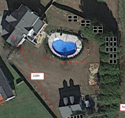
I thought i had the perfect spot to put my panels but i forgot that there is a power pole right in the middle of it! So it would be casting a shadow and i cant put panels under any type of power lines to my knowledge. 1702312356817.png


Now maybe the rules will change later and they'll let you expand the array, in that case if you oversize the wires appropriately you can turn one of those into 2P and put it on the 25A MPPT. Or pull extra sets of wires while you are trenching, maybe you can just fill it up completely to 6 or 8 conductors. 8 has the compromise of reducing the allowed ampacity compared to 6 so there's an extra cost penalty on top of the extra wire. The 18kpv has 4 inputs (2 into the same MPPT, so that could also be combined before bringing it to the inverter). More conductors is better if you might have extra inverters in the future b/c it is more flexible.
Even though wire isnt "cheap" it's not incredibly terrible. so i will run #6 conductors. not sure how many. Maybe 2x as many as required right now. Any reason to run ethernet out there? The trees have been cut down btw.
If you want to go entirely off grid, you’ll need a lot more granular information than you’ve posted so far. Simply using “average” demand/consumption for an 8-month period won’t cut it. You need to design a system built around handling PEAK demand at any given point.

1702312698431.png
i might get an Emporia power monitor that goes in the breaker box after Christmas. It will be great to know what kind of usage and surges i have. only problem is, i dont want to wait a year to collect the data!

If you want to go entirely off grid, you’ll need a lot more granular information than you’ve posted so far. Simply using “average” demand/consumption for an 8-month period won’t cut it. You need to design a system built around handling PEAK demand at any given point.
right now, definitely leaning toward a hybrid, system. stay under 10kw worth of panels, get a battery and either a 18kpv or a solark 15k. i have to read to see if it's worth the extra cost for the solark.
 
I thought i had the perfect spot to put my panels but i forgot that there is a power pole right in the middle of it! So it would be casting a shadow and i cant put panels under any type of power lines to my knowledge.
1702312356817.png
Where is this rule coming from? The power lines could well be either a short lived or consistent shade. I would think shingled or half cut would recover 50% in quite a few situations. Maybe the pole would only nuke 2-4 at a time depending on time of year and geometry. It's possible the loss from the shading could be comparable to the extra ground mount cost.

I'd create a post asking for shadow prediction apps, I saw a few posted here, I didn't save them because I know they won't do me any good.

i might get an Emporia power monitor that goes in the breaker box after Christmas. It will be great to know what kind of usage and surges i have. only problem is, i dont want to wait a year to collect the data!
NEC allows you to use 30 day data for load calculations as long as you're smart at making extrapolations from that 30 day data to the full year and don't have complications like battery or solar (strict prohibition), so presumably you're smarter than the intelligence level of practitioners that NEC assumes.

1702365175538.png

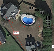
Are these trees gone? You might be able to string those 3 small arrays into the same MPPT (they need the same orientation), the disconnect switch at each array might be slightly trickier but probably solvable.

For the pictures with ground mounts property line, you need to check with AHJ on what the property line setback rules are. I don't think those would fly where I am.

Is this property a single meter with the bottom house getting the service drop, and then a feeder already trenched from there to the other house? if so then you could potentially put the backfeed there, and then the other house gets power via AC.

If the bottom house has the service drop, then putting the inverter there gets both houses emergency power. Putting the inverter at the top house may be OK too in this case if that's where you need the emergency power.

If the top house has the service drop, then putting the inverter at the bottom house would only give the bottom house emergency power (unless you do some expensive trenching & find some hardware to allow bottom house to disconnect grid at top house)

Even though wire isnt "cheap" it's not incredibly terrible. so i will run #6 conductors. not sure how many. Maybe 2x as many as required right now. Any reason to run ethernet out there? The trees have been cut down btw.

For those 150 ft lines the incremental cost of more conductors isn't really that much vs trenching in the firstp lace, you can go to 4 circuits without going deep into the derating hole. 80% from 4-6 current carrying conductors, 70% from 7-9 conductors. Ground excluded from current carrying. Spares must be counted as current carrying under current NEC.

If you want to go crazy with spares you need multiple conduits or separate direct bury cables. I feel like 4 should be pretty good.
 
Where is this rule coming from? The power lines could well be either a short lived or consistent shade. I would think shingled or half cut would recover 50% in quite a few situations. Maybe the pole would only nuke 2-4 at a time depending on time of year and geometry. It's possible the loss from the shading could be comparable to the extra ground mount cost.
I believe i read that they didnt want panels under the wires in case their wires dropped to the ground, onto the panels.

Are these trees gone? You might be able to string those 3 small arrays into the same MPPT (they need the same orientation), the disconnect switch at each array might be slightly trickier but probably solvable.
yes, the trees are gone. I had the panels divided into 12s and 13s in order to comply with the limits of the 18kpv. Also
wanted to separate the 3 small arrays because i think they will get some shade before the others toward the end of the day.

Is this property a single meter with the bottom house getting the service drop, and then a feeder already trenched from there to the other house? if so then you could potentially put the backfeed there, and then the other house gets power via AC.
Yes, a single meter drops into the larger house above the pool. the plan is to run power from the panels to the main house, where the inverters and batteries will be. the pool and the shop at the bottom of the image already has conduit and wires run to it, but not nearly what would be needed.
 
Can someone provide a resource for actual panel temperature prediction based on changing ambient conditions? I'm not seeing it. Maybe there's too many variables.

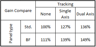
Also, I was wondering what kind of gains can i expect from single axis tracking AND bifacial gain.
I did some comparison on PVWatts.com. This is with the albedo set to .4. I searched around and found Everyday Dave on YT. He has some good data on BF panels, but no tracking yet. Realistically, i'll probably start with a fixed bifacial. I might mess around after that's up and running. I know you guys know this but, I set the standard panels without tracking as the reference, so it shows 100% (or 1). that doesnt mean it's producing 100% of its rating.

1702665832871.png
 
Last edited:
What year of International Residential Code is your state under? That's where the UL9540 rule comes in
Maybe i found something finally to answer this question: "...distributed generation equipment must meet current UL1741 and IEEE1547 requirements."

I see the EG4 18kpv meets both of these.
 
Last edited:
I believe 18kpv recently passed CEC approval (California Energy Commission) which is one of the tougher ones to get, and something that some other states rely on for their regulations (IE if approved by CEC then it's locally approved).
 
getting set up in my town is either going to be super easy or a complete disaster. There are only 3 lines of instruction for distributed generation in the "contractors manual".
 
Maybe the pole would only nuke 2-4 at a time depending on time of year and geometry. It's possible the loss from the shading could be comparable to the extra ground mount cost.
I wasn't planning on using optimizers(?) since i thought i didn't have any shading issues. if i were to put panels in the shade of the pole, wouldn't the whole string suffer? Or would the effect be negligible?

I like 12s and 13s, that lands the strings at the nominal voltage and minimizes the loss due to voltage drop.
Since open circuit voltage per 400w panel is 35-38vdc (based on the temp coefficient swing) wouldn't voltage for 12s be 428-464v and 13s be 463-502v (not accounting for 1.5% voltage drop)? the 18k says nominal pv input is 360vdc. What am i missing?

Edit: ( I think the higher voltage would be better to hit the min voltage sooner to start the inverter. And since voltage doesn't change with bifacial gain, only current, and I believe over-current will be clipped, maybe 12 & 13s would be better. )

Also, the spec for the 18k says "max short circuit current - 31/19/19A" and "max usable current - 25/15/15A". Does "max short circuit current" correspond to the Isc rating (13.55A) on the panel spec sheet? Seems like that would make sense. If so, wouldn't 8s2p and 9s work for a total of 25 panels? that would put voltage at ~300v and 335v. Min voltage for the inverter is 140v so maybe it's better to have the higher voltage?
 
Last edited:
I wasn't planning on using optimizers(?) since i thought i didn't have any shading issues. if i were to put panels in the shade of the pole, wouldn't the whole string suffer? Or would the effect be negligible?

If the MPPT does the right thing it will bypass all panels with shade on them (IE abandon all power from them). Sometimes it can recover part of the power. It depends on the geometry of the shadow and the geometry of how the solar panel is wired up internally between different sections.

With an optimizer you have potential to recover more. With the most advanced optimizers you can get the max you can get if the shaded panel was directly connected to an MPPT. Which could still be 0W depending on the shape of the shadow & geometry of the solar panel, it just factors out the interaction between different panels.

Optimizers also factor out the potential wear on the bypass diodes built into the back of the solar panel

Since open circuit voltage per 400w panel is 35-38vdc (based on the temp coefficient swing) wouldn't voltage for 12s be 428-464v and 13s be 463-502v (not accounting for 1.5% voltage drop)? the 18k says nominal pv input is 360vdc. What am i missing?
You look at Vmpp for the operating voltage. It is 6V lower per panel than Voc.

1704421590615.png

Also, the spec for the 18k says "max short circuit current - 31/19/19A" and "max usable current - 25/15/15A". Does "max short circuit current" correspond to the Isc rating (13.55A) on the panel spec sheet? Seems like that would make sense. If so, wouldn't 8s2p and 9s work for a total of 25 panels? that would put voltage at ~300v and 335v. Min voltage for the inverter is 140v so maybe it's better to have the higher voltage?

Yes max short circuit current is in reference to Isc on the spec sheet.

Yes you can also use 8s2p 9s, you will leave one 15A MPPT for other stuff. The 8s2p might clip if you really get Impp since that adds up to a little under 26A.

You want to keep a healthy margin above 140V for the summer, since voltage drops when it gets hot.
 
Such cool tech! I love it. I'm excited to get my hands on it.

I've tried to read up on the mppt's but I couldn't find a good explanation. And I had no idea there were bypass diodes in the panels themselves.

Has anyone tried to mount bifacials on the roof with a standoff bracket? If I could mount them a couple feet off the roof surface and whitewash my brand new shingles that would be great. Save ground space. But I haven't seen it.
 
Has anyone tried to mount bifacials on the roof with a standoff bracket? If I could mount them a couple feet off the roof surface and whitewash my brand new shingles that would be great. Save ground space. But I haven't seen it.
Anytime you deviate from putting panels parallel to roof (IE, boring as heck), it will invite more AHJ scrutiny and they WILL ask for engineering on it. When parallel to roof you can often get away with no engineering, just referencing a letter from the racking company saying that a parallel panel install meets applicable structural strength requirements.

Well I walk past a house in my neighborhood that has some truly massive standoffs to reverse the pitch (like 5 feet long, WTF), but it's a spec home and I'm sure money was no object.

I've tried to read up on the mppt's but I couldn't find a good explanation. And I had no idea there were bypass diodes in the panels themselves.
Bypass diodes are pretty critical to protect solar cells from damage when there is shade. Harvesting some extra power is secondary.

This is the kind of thing that most people have to read a bunch of times before it makes sense. For some people it never makes sense. Such is fate. There's some basic analog circuit analysis needed.
 
Anytime you deviate from putting panels parallel to roof (IE, boring as heck), it will invite more AHJ scrutiny and they WILL ask for engineering on it. When parallel to roof you can often get away with no engineering, just referencing a letter from the racking company saying that a parallel panel install meets applicable structural strength requirements.

Well I walk past a house in my neighborhood that has some truly massive standoffs to reverse the pitch (like 5 feet long, WTF), but it's a spec home and I'm sure money was no object.


Bypass diodes are pretty critical to protect solar cells from damage when there is shade. Harvesting some extra power is secondary.

This is the kind of thing that most people have to read a bunch of times before it makes sense. For some people it never makes sense. Such is fate. There's some basic analog circuit analysis needed.
Just read a great article on bypass and blocking diodes. I'm still not fully grasping all the functional differences between bypass diodes and optimizers. I get that the diodes protect the panels and optimizers optimize output, just seems like the diodes are also optimizing output when they bypass the shaded panels. I'll keep reading.
 
Just read a great article on bypass and blocking diodes. I'm still not fully grasping all the functional differences between bypass diodes and optimizers. I get that the diodes protect the panels and optimizers optimize output, just seems like the diodes are also optimizing output when they bypass the shaded panels. I'll keep reading.
The diodes work with the string MPPT on the inverter to achieve the optimization.

The protection mechanism on the diodes is to give an easier path for current vs blowing through a section of the panel. Without it, there is potential for excess unused current to blow through the parasitic diodes that the solar cells (which is not good for them).
 
Tracking takes up too much room! They block each other when you start moving them around. I think i'm just going to have to fix them in place.

Also, i think it makes sense for me to set my panels at the summer angle (13.8 degrees) since i use more power in summer (Electric AC, Gas heat...for now) and panels are less efficient in summer. I'll still space them out to get the best albedo, but definitely thinking they need to be fixed.

I need to go into the Electric company next week and see what they need as far as plans. Not sure what kind of detail and professionalism they require.
 
Last edited:
Tracking takes up too much room! They block each other when you start moving them around. I think i'm just going to have to fix them in place.
There are some threads where folks put a large number on a single tracker to deal with this (it's a tradeoff i think between mechanical strength/complexity and wasted space). If you have the spare land between solar panels to handle a bunch of small trackers, you could also just install more fixed solar panels and overpanel / let it clip.

Some special cases like single axis manual tracking are pretty space efficient, there are some people that change the angle to be more vertical in the winter vs more horizontal in the summer.
 
If you have the spare land between solar panels to handle a bunch of small trackers, you could also just install more fixed solar panels and overpanel / let it clip.
No extra land, and the city limits me to 10kw of panels. Trying to stay out of the middle of the yard, stay in the sun.
Some special cases like single axis manual tracking are pretty space efficient, there are some people that change the angle to be more vertical in the winter vs more horizontal in the summer
If I did tracking at all it would probably be single axis with a manual winter/ summer adjustment. I have a north/ south fence line that I could put a row of panels on a long bar with single axis.

Fun stuff.
 
Back
Top