diy solar

diy solar

LVX6048WP Setup Issues and Warning Codes

I'll email it to you. As far as I know the only change to it was to fix my W13 warning for low battery voltage. Did you have this issue? Did you ever have a flashing battery icon and brackets on the top portion of the screen with 42V?

I'll have to try turning the strings on one at a time later today. I'll have to get back to you on how my strings are wired as well, I don't seem to have any pictures of it. Has your system ever actually produced power and fed it back to the grid?

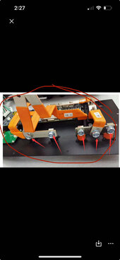
I did find that the Solar Power Store appeared to wire the combiner box incorrectly. They had the positives and negatives for both strings swapped going from the surge protectors into the DC disconnect. When I wired from the DC disconnect to the inverter, I just connected everything as per the labels on the disconnect switch. The positions of the positives and negatives flip sides from the top to the bottom of the switch. Fortunately I caught this before I turned the PV power on to the inverter, not sure what would have happened if I turned it on with the polarity reversed. Might be something to double check.
 
@YotaPower yes been running power since last September. F13 became an issue early winter when I did a firmware upgrade and clearly should not have. I have never had the W13 warning. Only the F13 ISO fault.

My combiner box is likely very different than yours. With shortages last year they sent me 2 - 1 in and 1 out boxes instead of 1 - 2in 2out boxes. I wish I had yours.

I just swapped the cables to the right side instead of left side on port. Didn't help. I will update to V1.35 and im hoping that gets rid of the 24/7 fan running 100%.

What I find so crazy is 2 days ago the F13 ISO fault was completely resolved. When I flipped the PV disconnect switch to 'on' I literally watched it power up each string at a time. It was as if V1.34 fixed it and I watch the display turn on one strings amperage.. then turn on the next string amperage about 20 seconds later. I think the mistake I made was turning the Inverter off completely last night because the fan was screaming 100% since upgrading to 1.34.. and its like it completely forgot the next day how to fire up each string separately because now it trying to turn both strings on at the same time and F13 Fault kicks.

@YotaPower im sorry to hear you havent even generated anything with this inverter yet. I am happy to do a factime/zoom call with you and I can take a look at your set up to see if anythings if different from mine. Trying firing up one string at a time for now using the DC breakers open the combiner box and let me know if that helps. Thats the only way I can get mine to work for now.
 
Hi guys,

I have two LVX6048WP and had a problem with one of them from last October until today. Not the same fault as you are having. It was slow going but MPP service in Taiwan kept sending boards until we got to the remote board which solved the problem. It was slow going but they kept at it and I've almost got a whole set of replacement boards for my trouble.

After thinking about the PV ISO fault problem you are having, I was wondering if it could be the type of lightning arrester that you are using on the panel circuit.

You may have tried this already but if not try disconnecting the lightning arrester.

Thanks for sharing your experiences!
interesting, i never thought it could be related to that. i spoke with @YotaPower and we both have different combiner boxes, but same brand. i got it it resolved for now as per this thread but maybe one day when i’m bored i’ll put it back to grid tie ‘only’ and remove combiner box temporarily to see if that could be it.


what was wrong with your one inverter ? we they both same build time? curious is your serial number has 2204 in the middle as it seems april 2022 inverters have had the issues.
 
One new build and one old. The old build inverter failed after a few weeks of noisy DC bus faults. Eventually the display quit working and the inverter would shut down about 50 seconds after starting it up. After many attempts at trying to connect with wifi and rs232 MPP shipped the controller, the charger and inverter boards. I installed the new boards but it didn't change anything. The display was still dark and the inverter still shut itself off after 50 seconds.
I tried updating the firmware but it kept shutting down while the download was still in progress.
After I sent MPP service a video of what was happening, they decided to send the remote board. (Board mounted on the fan) When I swopped it out and started up the display came back and the inverter was back to normal.
I set the inverters up in parallel with no grid power and had them powering a test load in the garage. It was all good like this overnight and this morning but I checked this afternoon and the inverters were faulted with an error code of 72.
No idea what that code is. Checked the history on Solarpower ( haven't been able to connect the older firmware one to wifi yet). The solar input got up to 6 KW so maybe that's what tripped them out. We'll see what happens tomorrow.
I'll keep testing.
 
@Gib Sorry, just seeing your message now about the lightning arrestors. Would these be the surge protectors that are in my combiner box or something else? I've never heard of them before? I have a grounding plate buried outside that is tied directly to my 200A main panel, the same panel the inverter is wired to.

I have followed what Kyle has done and was able to get the inverter to generate power if I flashed the firmware back to 1.23 and left it in "grid tie with battery" mode. It still beeps constantly because of the low battery voltage warnings. I also do not get coherent power generation data from either the inverter itself or the SolarPower App.

MPP has been very frustrating to deal with, they gave me a two week timeline to provide a firmware fix, which never happened. They are now trying to say its a grounding issue, which isn't the case if I'm able to get the system working (kind of) with older firmware.

At this point I'm done with this science project, I have officially asked for a refund from the Solar Power Store as the unit has never worked properly since day one. Based on the interactions I've had with them so far, I am expecting it to be a fight to get my money back. Based on my experience with both MPP Solar and the Solar Power Store, I STRONGLY suggest you stay far, far away from both companies.

If anyone else has purchased this inverter from the Solar Power Store and has had issues with it, please let me know!
 
Hi @YotaPower ,

Your experiences with the Solar Power Store, the LVX6048WP and MPP are discouraging. I'm on the same path that you went down. At the moment I'm waiting for another waranty replacement board from MPP.

I was talking about the devices in the combiner box. The arresters are designed to pass current to ground when activated by high voltage. I haven't looked at the design of the ones the Solar Power Store sold me but I have come across arresters used in the telephone industry that developed leakage to ground.

I don't know what method the inverter is using to detect a ground on the solar panel circuit. So temporarilly disconnecting the arrester was one way of testing to see if that was causing the fault.

I'd be interested in hearing how things work out for you with Solar Power Store.

Thanks,

Gib
 
Disregard KTime, after 2 weeks of screwing around with various settings, I have managed to get the inverter to actually charge the battery bank and run all loads.

Further, I'm going to attach the settings I have had to use in hope that it will save someone else the frustration I have had to endure since installing this inverter. I've been living off grid for 12 years, this MPP inverter has had to be the most unfriendly piece of kit I have had to install and trouble shoot. It partially started with the manual in the box, it was version #1, and after I upgraded to the most current software I was on version 1.4, mind you I did not know that some of the settings had changed and or been added, which just made it all the more challenging. Couple that with poor tech support, which consists of 1 email per week when you factor in business hours and the time change to China. Knowing what I know now, I should have just gone with name brand gear and saved myself a lot of trouble, and fuel running my generator for a week straight.

I have the SOK batteries (500a bank) and managed to set them up to communicate fine, even got the 6048 to connect to them under Pylon 485, but the inverter would not power up, it had to be set to "USE". This kind of negates the whole concept of having your batteries communicate with your inverter for maximum efficiency etc. I was set on OFF Grid #1 and had made all kind of adjustments, did all kinds of research (how I ended up here), watched way more youtube videos than is probably good for one person, then stumbled upon the fix. After trying what I figured was every other option, I decided to change the off grid settings, #2 didn't fit my needs well, but I thought I'd give #3 a go, miracle upon miracles and I was in business. Why it wouldn't work on #1 or #2 is beyond me, doesn't make any sense what so ever, but after 2 weeks of this I wasn't touching anything!

I have since tried re-connecting with the batteries and Lithium settings via the supplied cables etc, still no love there, frankly I can live without that feature, the batteries BMS will take care of themselves. If anyone is interested, my Honda eu6500si powers the charger and all loads with ease, right up to the full 120 amps (tested). However, you have to start the generator with the ECO Throttle in the Off position, or there won't be enough ooomf to connect and get up and charging, it just keeps dropping out as per what you will see on the screen. I have an auto start system that allows me to start up with eco off and after 10 minutes of warm up, it will turn it on and the generator and inverter/charger adjust and keep going fine. I will be installing another 4,000 watts of solar once the snow melts, hoping to eliminate any generator use in the winter time, we'll see.

One of the worst things about this inverter is the Noise, the fans are on 24/7, it sounds like somebody walked into your home with a Leaf Blower going and just left it on the floor for you to enjoy! I actually pulled out my sound meter to get a reading, it's 70 decibels, just for shits and giggles I went outside to test the sound of my exhaust on the generator, it was 68, how crazy is that. The generator doesn't actually sound that bad, it's kind of low rumble, not the inverter, it's just down right annoying, we have to power it off at night just so we can sleep. I thought about putting this thing outside because it's supposedly water resistant, but if I'm sitting down by the lake having a beverage, I don't want to listen to it out there either. I ordered up some thermostats and a couple of Noctua fans, hopefully in a couple of weeks I will have some peace and quiet back. The fan noise is enough for me to NOT recommend this to anyone, unless this is going in an out building somewhere, even then it would suck to have to work in that space. Think twice before you buy this thing.

Kevin
Thanks for sharing your settings! I’ve been having so many issues with the 6048wp settings as well and Watts247 lacks support.

Im curious why you enabled #34-Wide AC input range, did this help?

For #15 are you saying the generator is the utility?

Did you notice a difference between bAd and bAE for #31? (odd it’s E for disabled in the manual). I have DIY battery cases from Docan on Alibaba so I am assuming I need to change to bAE.

image.jpg


Below are my settings. Today I kept getting either F01 or warning 15. The batteries are disconnected until I crimp 2/0 so I was trying to run on solar only. I tried many different variations including USE and LIC,
IMG_7621.jpegAfter hours I continued to just receive these errors without luck. Couldn’t even charge my phone. If anyone has any recommendations I am all ears!!

IMG_7612.jpeg
IMG_7613.jpeg

My system:
I am off-grid, with 6 LVX 6048wp in parallel. I have 3 Alibaba Docan 48V Apexium DIY boxes (side note to anyone: I do not recommend these boxes as the app user interface is weak. To make matters worse one of the terminals already melted. I am hardwiring a 2/0 lug instead of those plastic terminals.) While Docan has great customer support, no amount of support can make up for how unreliable these DIY boxes are. Should’ve stuck with an overkill BMS and a storage container.

IMG_7587.jpeg
IMG_7589.jpeg
 
Last edited:
Thanks for sharing your settings! I’ve been having so many issues with the 6048wp settings as well and Watts247 lacks support.

Im curious why you enabled #34-Wide AC input range, did this help?

For #15 are you saying the generator is the utility?

Did you notice a difference between bAd and bAE for #31? (odd it’s E for disabled in the manual). I have DIY battery cases from Docan on Alibaba so I am assuming I need to change to bAE.

View attachment 192543


Below are my settings. Today I kept getting either F01 or warning 15. The batteries are disconnected until I crimp 2/0 so I was trying to run on solar only. I tried many different variations including USE and LIC,
View attachment 192547After hours I continued to just receive these errors without luck. Couldn’t even charge my phone. If anyone has any recommendations I am all ears!!

View attachment 192541
View attachment 192542

My system:
I am off-grid, with 6 LVX 6048wp in parallel. I have 3 Alibaba Docan 48V Apexium DIY boxes (side note to anyone: I do not recommend these boxes as the app user interface is weak. To make matters worse one of the terminals already melted. I am hardwiring a 2/0 lug instead of those plastic terminals.) While Docan has great customer support, no amount of support can make up for how unreliable these DIY boxes are. Should’ve stuck with an overkill BMS and a storage container.

View attachment 192544
View attachment 192545
Looks to me like your 6 inverters are pulling too much current from your battery connections. The supplied cables may not have been properly crimped. Note that instead of swapping the existing terminals, you can just add another cable connection to each battery to your parallel busbar.
I recommend the Blue Sea 1000 amp busbars to be safe. Are you monitoring the peak amps from your batteries to make sure the power is spread evenly?

I use solar assistant for that, and it works great. (Although I dont have comms from batteries to the inverters).

The copper also looks like there may be some moisture attacking your connections.
 
Sanwizard appreciate your detailed reply!
Looks to me like your 6 inverters are pulling too much current from your battery connections. The supplied cables may not have been properly crimped.
It wasn’t crimped. The instruction video they provided didn’t crimp. I was able to pull (hard) the 2ga wire right out of the terminal. Docan said that it was likely caused by these connections being loose, but I remember tightening them well. I’ll check them when I open up the boxes

Note that instead of swapping the existing terminals, you can just add another cable connection to each battery to your parallel busbar.
Can you help clarify what you mean by add another cable connection? I was planning to crimp my own 2/0 lugs today to get back online, something else? Daisy at Docan said I can put the wire right through the hole and connect directly.
I recommend the Blue Sea 1000 amp busbars to be safe.
Yes actually that’s is what I’m using. I may have made a mistake though with connecting the inverters and batteries having random locations on the busbars? I’m going to adjust the wire locations so all have identical positive and negative stud locations to be sure. This is my first double decker busbar
IMG_7177.jpeg

Are you monitoring the peak amps from your batteries to make sure the power is spread evenly?
I use solar assistant for that, and it works great. (Although I dont have comms from batteries to the inverters).
I have solar assistant as well! However I just got the correct coms cables between SA and the batteries/inverters. I have been using a battery com cable I bought from Watts247, but sometimes it would just not report values. I got the correct cables from SA now. What do you monitor in SA to ensure evenness?

Have you figured out the Advanced settings?
The copper also looks like there may be some moisture attacking your connections.
It may be possible and I’ll inspect the area closer. How do you tell by the look?
 

Attachments

  • IMG_7664.jpeg
    IMG_7664.jpeg
    57.3 KB · Views: 1
Sanwizard appreciate your detailed reply!

It wasn’t crimped. The instruction video they provided didn’t crimp. I was able to pull (hard) the 2ga wire right out of the terminal. Docan said that it was likely caused by these connections being loose, but I remember tightening them well. I’ll check them when I open up the boxes


Can you help clarify what you mean by add another cable connection? I was planning to crimp my own 2/0 lugs today to get back online, something else? Daisy at Docan said I can put the wire right through the hole and connect directly.
Each battery has two positive and two negative terminals. I am assuming they are similar to my Seplos boxes, and they are connected by a busbar internally. This means you can use 4 cables per battery(2 x pos and 2 x neg) to the blue sea busbar. I would NOT remove the terminal to pull a cable inside.
Yes actually that’s is what I’m using. I may have made a mistake though with connecting the inverters and batteries having random locations on the busbars? I’m going to adjust the wire locations so all have identical positive and negative stud locations to be sure. This is my first double decker busbar
View attachment 192638

I have solar assistant as well! However I just got the correct coms cables between SA and the batteries/inverters. I have been using a battery com cable I bought from Watts247, but sometimes it would just not report values. I got the correct cables from SA now. What do you monitor in SA to ensure evenness?

Have you figured out the Advanced settings?

It may be possible and I’ll inspect the area closer. How do you tell by the look?
I like the idea of consistency in the connections. Make sure you torque the cables the same also. As for the copper being moist, I can see the copper turning green where your cable started to melt. Green means moisture and corrosion.

Solar assistant shows the current draw during discharge, and flow into each battery during charge. During charge, the total current should spread evenly across each battery. If not, then there is probably a resistance difference somewhere.

Also, make sure to test your breakers, and that they will trip before your DC cables melt!

I like your Unistrut rack! (Although I dont like having cells on their sides. I like the cell terminals pointing up).
 

Attachments

  • 20230730_181335.jpg
    20230730_181335.jpg
    187.1 KB · Views: 3
  • 20230730_181145.jpg
    20230730_181145.jpg
    183.3 KB · Views: 3
  • 20230730_181207.jpg
    20230730_181207.jpg
    122.3 KB · Views: 3
Each battery has two positive and two negative terminals. I am assuming they are similar to my Seplos boxes, and they are connected by a busbar internally. This means you can use 4 cables per battery(2 x pos and 2 x neg) to the blue sea busbar. I would NOT remove the terminal to pull a cable inside.

I like the idea of consistency in the connections. Make sure you torque the cables the same also. As for the copper being moist, I can see the copper turning green where your cable started to melt. Green means moisture and corrosion.

Solar assistant shows the current draw during discharge, and flow into each battery during charge. During charge, the total current should spread evenly across each battery. If not, then there is probably a resistance difference somewhere.

Also, make sure to test your breakers, and that they will trip before your DC cables melt!

I like your Unistrut rack! (Although I dont like having cells on their sides. I like the cell terminals pointing up).
Oh, and make sure your not super charging your batteries. With SIX inverters, the manual calls for 1200ah. So around 1 battery per inverter. If you have fewer, drop the max charge current to around 30amps or less per inverter.
 
Each battery has two positive and two negative terminals. I am assuming they are similar to my Seplos boxes, and they are connected by a busbar internally. This means you can use 4 cables per battery(2 x pos and 2 x neg) to the blue sea busbar.
Ah great to know, I wish I knew this earlier! I thought the second one was if you were going to directly parallel the boxes to each other. This was my first box kit. In the past, I DIYed my own compression and used overkill Solar BMS.

I still don’t understand how it melted the terminals because the BMS is supposed to have protection in placeIMG_7669.jpeg
IMG_7587.jpeg
I would NOT remove the terminal to pull a cable inside.
Can you explain what concerns you? I’m remote off grid and have 4 of their terminals remaining. I have plenty of #2 and 2/0 gauge copper lugs. Kind of my only option to have the three batteries be consistent. WindyNation, 2/0 is rated up to 285 A, while there two gauge wire is rated up toBut I definitely want to be safe.
I like the idea of consistency in the connections. Make sure you torque the cables the same also. As for the copper being moist, I can see the copper turning green where your cable started to melt. Green means moisture and corrosion.

Solar assistant shows the current draw during discharge, and flow into each battery during charge. During charge, the total current should spread evenly across each battery. If not, then there is probably a resistance difference somewhere.
You rock
Also, make sure to test your breakers, and that they will trip before your DC cables melt!
Perhaps I made a mistake in my design. I oversized the breakers because I was planning to pull up to 0.7 C. I have three breakers at 250 A. Do you think it would be better to use one positive and one negative 2/0 or #2 gauge using the two positive and two negative for each battery, connecting the two positive #2 to the 250 amp breaker for each battery? Unless you still strongly advise against this, even though I don’t have enough of their compatible popon terminals?
I like your Unistrut rack!
Thanks! I designed the whole trailer from the flatbed up. All the Unistrut was pre cut for a quick assembly at the property like legos lol
IMG_7654.jpeg
So this system actually I wanted to run it battery-less. It’s designed to only run during the day. I’ve had plenty of time the past few days but still haven’t been able to figure out the battery-less settings, just errors. No mention of this in the manual either even though it is listed on MPP’s website. Two of the three settings are grid tied and i’ve been using OFG off grid, OFGIan from Watts247 said that the off grid setting expects a battery present.

I have a second raspberry pi that uses MQQT to fetch data from SA, but as mentioned, the battery data has been sporadic until now that I have the proper comms cables. Based on the data reported by SA the second raspberry pi will send commands to increase or decrease the power consumption of the equipment between a range of 10,000-32,000 W. With this running during the day, most of the heavy lifting should come from the panels, at least that’s the plan. Really once the system detects an average drop in PV production, the power consumption will be reducing the opposite is true for when it is increasing. So pulling the entire load from the batteries just should not happen and that’s something I need to examine. You’re right SA has a lot more data than the original cable I was using.

(Although I dont like having cells on their sides. I like the cell terminals pointing up).
Yeah, I didn’t like this either, but it was the only way to make them fit. I confirmed this with Docan and their engineer said it wouldn’t be a problem. The engineer also said that given my current situation, without enough, pop on connectors, I could hardwire with copper lugs instead of using the pop on connectors.

I appreciate your feedback and looking forward to your response.
 
Last edited:
Ah great to know, I wish I knew this earlier! I thought the second one was if you were going to directly parallel the boxes to each other. This was my first box kit. In the past, I DIYed my own compression and used overkill Solar BMS.

I still don’t understand how it melted the terminals because the BMS is supposed to have protection in placeView attachment 192769
View attachment 192770

Can you explain what concerns you? I’m remote off grid and have 4 of their terminals remaining. I have plenty of #2 and 2/0 gauge copper lugs. Kind of my only option to have the three batteries be consistent. WindyNation, 2/0 is rated up to 285 A, while there two gauge wire is rated up toBut I definitely want to be safe.

You rock

Perhaps I made a mistake in my design. I oversized the breakers because I was planning to pull up to 0.7 C. I have three breakers at 250 A. Do you think it would be better to use one positive and one negative 2/0 or #2 gauge using the two positive and two negative for each battery, connecting the two positive #2 to the 250 amp breaker for each battery? Unless you still strongly advise against this, even though I don’t have enough of their compatible popon terminals?

Thanks! I designed the whole trailer from the flatbed up. All the Unistrut was pre cut for a quick assembly at the property like legos lol
View attachment 192773
So this system actually I wanted to run it battery-less. It’s designed to only run during the day. I’ve had plenty of time the past few days but still haven’t been able to figure out the battery-less settings, just errors. No mention of this in the manual either even though it is listed on MPP’s website. Two of the three settings are grid tied and i’ve been using OFG off grid, OFGIan from Watts247 said that the off grid setting expects a battery present.

I have a second raspberry pi that uses MQQT to fetch data from SA, but as mentioned, the battery data has been sporadic until now that I have the proper comms cables. Based on the data reported by SA the second raspberry pi will send commands to increase or decrease the power consumption of the equipment between a range of 10,000-32,000 W. With this running during the day, most of the heavy lifting should come from the panels, at least that’s the plan. Really once the system detects an average drop in PV production, the power consumption will be reducing the opposite is true for when it is increasing. So pulling the entire load from the batteries just should not happen and that’s something I need to examine. You’re right SA has a lot more data than the original cable I was using.


Yeah, I didn’t like this either, but it was the only way to make them fit. I confirmed this with Docan and their engineer said it wouldn’t be a problem. The engineer also said that given my current situation, without enough, pop on connectors, I could hardwire with copper lugs instead of using the pop on connectors.

I appreciate your feedback and looking forward to your response.
Ian is correct. Off grid needs a battery. Thanks for the pic of your solution, as it clears up a lot. I can see why there may be moisture. I hope you have a shed or something to put over the inverters.

Although they are labled WP, I would not trust them with full exposure to wind driven rain. IP65 is water resistant, not waterproof. (Maybe build a shed enclosure around them?)

The manual states you need 1200ah with six inverters. Your current draw from the batteries, and the charge settings from the six inverters are probably too high.

Try setting your charge and discharge current limits to 30 amps to start, and then check your cables for heat. (Settings 04 to 06 in the manual).

I like the 2/0 cable idea if possible, but with so few batteries supporting six inverters, It may be more cost effective to just set the inverters to Grid Tie only, so you dont have to worry about all those settings. Use the batteries for emergency backup only( or add more batteries if possible).
My inverters are version one hardware and thw old firmware, so it may be best to get assistance from MPP for your grid tie only settings and why you are getting errors. Use the latest MPP Solar Power software on a connected PC to change the settings. (The mobile app seems to have limits).

There is a guy on Youtube who is doing grid tie only, so I know it works on these units. (I will try to find the link to his channel for you).
Good luck!
Hey, so in case if someone comes along with a similar struggle …

I made some progress isolating the issue. I was able to get 5 of the 6 inverters to run in SIG on their own and the AC output worked both with and without the battery.

However, when I switch to parallel mode, there was no AC output. One inverter flashes F01 and the other flashes warning 15. Then it dawned on me that the parallel wires were not arranged for only 2 inverters and it was never going to work. Uh duh. The last couple days I was using only 2 or 3 of the inverters in parallel mode to troubleshoot.

I then switched all 6 back to SIG one by one with the others turned off. I then turned all back on at the same time and began going around changing each to parallel mode. I ran out of sunlight, but I wanted to verify I am doing the process correctly. If anyone familiar with how to put lvx6048wp into parallel, is this the right process going forward per the manual:

1) All inverters are set to SIG
2) Turn on ALL inverters and then change each to PAL
3) Reboot all and then if I don’t get any errors, I’m good to go

IMG_7731.jpeg

For inverter three that wouldn’t work in SIG or PAL, it appears to be a battery cable issue to the busbar. It was showing 48v here while the others showed 55.6v as seen below:IMG_7715.jpeg

Inverter three would not cold start once the sun was down so I’m going to check the battery cables. From the wiring diagram in the manual, it would be here.
IMG_7733.jpeg
Inverter five was also experiencing a F32 when placed into parallel, maybe from the parallel communications coming from inverter three, I hope.

I’ll update if it was indeed the battery cables for inverter three after checking tonight. Also, if this resolved the F32 with inverter five.
 
Hey, so in case if someone comes along with a similar struggle …

I made some progress isolating the issue. I was able to get 5 of the 6 inverters to run in SIG on their own and the AC output worked both with and without the battery.

However, when I switch to parallel mode, there was no AC output. One inverter flashes F01 and the other flashes warning 15. Then it dawned on me that the parallel wires were not arranged for only 2 inverters and it was never going to work. Uh duh. The last couple days I was using only 2 or 3 of the inverters in parallel mode to troubleshoot.

I then switched all 6 back to SIG one by one with the others turned off. I then turned all back on at the same time and began going around changing each to parallel mode. I ran out of sunlight, but I wanted to verify I am doing the process correctly. If anyone familiar with how to put lvx6048wp into parallel, is this the right process going forward per the manual:

1) All inverters are set to SIG
2) Turn on ALL inverters and then change each to PAL
3) Reboot all and then if I don’t get any errors, I’m good to go

View attachment 193452

For inverter three that wouldn’t work in SIG or PAL, it appears to be a battery cable issue to the busbar. It was showing 48v here while the others showed 55.6v as seen below:View attachment 193455

Inverter three would not cold start once the sun was down so I’m going to check the battery cables. From the wiring diagram in the manual, it would be here.
View attachment 193454
Inverter five was also experiencing a F32 when placed into parallel, maybe from the parallel communications coming from inverter three, I hope.

I’ll update if it was indeed the battery cables for inverter three after checking tonight. Also, if this resolved the F32 with inverter five.
Sounds like your on the right track. Let us all know what happens, as I think you have the largest LVX6058WP install so far of any on this forum!
 
Back
Top