diy solar

diy solar

Making 8AWG PV to SCC wires

Oh look it's a Kombiner! ☮

Patent Pending? ;)

Confession, out of the three seperate solar systems that are on operation here at petticoat junction, mine has the absolute worse wire run. It consists of about 40' of #6 copper submersible water pump wire

You mean you didn't run romex over a gravel driveway and through the yard, running over it with the lawn mower and couldn't figure out why the lights wouldn't come on?
YUP! I saw it... :poop:

On another forum, a guy was asking if he could run his power lines through the water pipe so he didn't have to buy conduit... :rolleyes: (n)
I don't go there anymore, guys were actually trying to figure out how to do it.

I watched a 'BoobTube' video about 'Easy' utilities, the guy ran natural gas, power & water in the same trench...
AND was going to use black plastic water pipe for the gas line.
I guess he wanted to see flames shoot out of a water filled hole when it blew up...
I'll bet the code guy had a field day with him!

Old dogs have a hard time with new tricks,
But you can't teach a STUPID dog anything.
 
Last edited:
Patent Pending? ;)


You mean you didn't run romex over a gravel driveway and through the yard, running over it with the lawn mower and couldn't figure out why the lights wouldn't come on?
YUP! I saw it... :poop:

On another forum, a guy was asking if he could run his power lines through the water pipe so he didn't have to buy conduit... :rolleyes: (n)
I don't go there anymore, guys were actually trying to figure out how to do it.

I watched a 'BoobTube' video about 'Easy' utilities, the guy ran natural gas, power & water in the same trench...
AND was going to use black plastic water pipe for the gas line.
I guess he wanted to see flames shoot out of a water filled hole when it blew up...
I'll bet the code guy had a field day with him!

Old dogs have a hard time with new tricks,
But you can't teach a STUPID dog anything.
All I can say is that beer has a time and a place! ?
 
Its highly overrated in pv wire. The insulation is quite inpenetratable to moisture. The terminals are tinned and that is the point to keep corrosion free. Think of buried ground conductors. They can be under and in ground contact for a hundred years without issue. Larger strands, but...
 
Thanks everyone for the replies,
After everyone's input and watching some vids, I really like the idea of a waterproof junction box and some DIY engineering with a couple bus bars, glands, Dicor, Eternabond, etc. Gives me the ability to do a really nice seal through the roof, and leave room for changes/ expansions.
 
It works. One of my array home runs makes way through the roof deck on our garage with a junction layed on the shingle.... its a temp in on a new array. I used a pvc male thread adaptor fitting in the back of a 6" square pvc shallow outdoor junction box and two 2-hole Heyco strain relief fittings (cord grip with gland) black nylon.
I bought a nice junction with the quarter turn retainer tabs, easy to get into and heavy. 14$ though at local electric supplier.

Goop ring of neoprene roof caulk (temp in....) around the "T/A" fitting and screw down to roof deck.

First install of the season ill have a soladeck in the order and replace the improper passthrough.

Flashed pv mount attachements and flashed roof deck pass throughs are forever. Your building would eventually be a moulder pile around the pristine flashed components of you left them indefinitely. :)
 
Last edited:
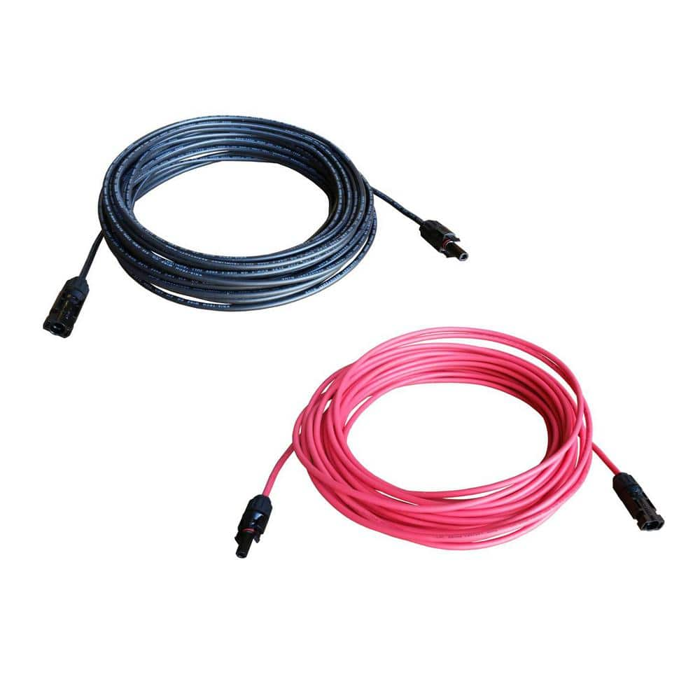
Im considering going with 8AWG PV to SCC wires instead of 10AWG. But all of the crimping tools and MC4 connectors only go up to 10AWG. How are you'all making your 8AWG wires?

Have you actually done the math/calculations and determined that you truly need 8 AWG?? Nice to have (8AWG) usually doesn't help you much when (10AWG) is all that is required... I'm going to bet that if you did a realistic power-budget ... 8AWG would work fine ...
 
Have you actually done the math/calculations and determined that you truly need 8 AWG?? Nice to have (8AWG) usually doesn't help you much when (10AWG) is all that is required... I'm going to bet that if you did a realistic power-budget ... 8AWG would work fine ...
You mean 10 AWG would work fine ?? ;-)
 
Have you actually done the math/calculations and determined that you truly need 8 AWG?? Nice to have (8AWG) usually doesn't help you much when (10AWG) is all that is required... I'm going to bet that if you did a realistic power-budget ... 8AWG would work fine ...
Use a voltage drop calculator...... dont not use it and "go upsize" on this and that conductor set out of hearsay and emotion.

Know all wire lengths, round up to the nearest couple five feet in order to roughly account for terminations at least. You could measure them, bit likely no need.
Use the calculators!!!..... on all circuits.

The best exercise is to take someone aside (your electrician?) And show them in no uncertain terms that ac and dc have the same voltage loss in a given conductor with the same voltage and current! Its a noodle scrambler to some!

this HTML class. Value is http://www.nooutage.

Man these link issues....

Type nooutage volt drop calculator. I have used many, bit this one has been used on over a hundred successful systems of mine. And used to smash company electricians arguing for 3% loss circuits..... cant tell you how many times. Convienient amd easy to use.
 
You mean 10 AWG would work fine ?? ;-)

I'm saying that you need to measure the distance from EACH of your solar cells and cables to the demarcation point ... you will also need to know the amperage of each of your cells ... I'm not sure what distances you are running .. but there are simple charts where you can find the size of wire you need ... going larger simply to go larger does nothing for you -- there is a "right" size (AWG) for most applications .. and again - that's based on distance and amperage ...
 
I’m trying to decide if I should use 10 gauge from my PV array with a 3% voltage drop, or 8 gauge with a 1% voltage drop. Is the 2% really worth the money of the thicker gauge wire?
 
I’m trying to decide if I should use 10 gauge from my PV array with a 3% voltage drop, or 8 gauge with a 1% voltage drop. Is the 2% really worth the money of the thicker gauge wire?
Yes, it has to do with making the most of the available power. Over time a couple percent adds up. Also some circuits rely on low loss for calculation amd response to the system requirements.

2% has long been the t%arget for proper pv wiring and acceptable loss. 3% is maximum legal loss. It also creates heat inside enclosures at terminals, inside conduit amd if you go above this line, it increases likely hood of fault or improper/unsafe operation.

1% or less on all grid tie inverter ac bi-directional circuits. 1% charge controller circuit, 1-2% ac output and generator circuits.

Wire is usually actually cheap and it is permanent performance. I will do 1% where practical and affordable.
 
Have you actually done the math/calculations and determined that you truly need 8 AWG?? Nice to have (8AWG) usually doesn't help you much when (10AWG) is all that is required... I'm going to bet that if you did a realistic power-budget ... 8AWG would work fine ...
Correct me if I me wrong , which I could very well be ! This is for a 30' Toy Hauler RV
My plans are for 4 100w 2s/2p which gives me ~ 36.4v 11A at the SCC . Ive been using this chart https://www.bluesea.com/resources/1437 I've estimated about a 25' run ( one way ) so 50' round trip if I use the "wired for solar" existing 10AWg wires which would require splicing into them at the AC/DC panel ( where they come out of the wall ) and extending the PV wires to the front of the RV where the SCC / Inverter/ batteries are. This puts me in the 6AWG range if I use the 15A column !
I think I might just use 10AWG and drill a new hole in the roof to accommodate the shortest run using the above combiner box to run wires in the roof leaving me room to add more panels if I want. Sorta like in this video , I dont know about the all the other stuff this guy does but I like the way the combiner box has the wires going through the roof/ allows access unlike those Solar "gland" availabe .
.......thoughts?
PS Ive made some changes to my blue print but this is the general idea.
 

Attachments

  • solarbluep1.jpg
    solarbluep1.jpg
    109.3 KB · Views: 2
Correct me if I me wrong , which I could very well be ! This is for a 30' Toy Hauler RV
My plans are for 4 100w 2s/2p which gives me ~ 36.4v 11A at the SCC . Ive been using this chart https://www.bluesea.com/resources/1437 I've estimated about a 25' run ( one way ) so 50' round trip if I use the "wired for solar" existing 10AWg wires which would require splicing into them at the AC/DC panel ( where they come out of the wall ) and extending the PV wires to the front of the RV where the SCC / Inverter/ batteries are. This puts me in the 6AWG range if I use the 15A column !
I think I might just use 10AWG and drill a new hole in the roof to accommodate the shortest run using the above combiner box to run wires in the roof leaving me room to add more panels if I want. Sorta like in this video , I dont know about the all the other stuff this guy does but I like the way the combiner box has the wires going through the roof/ allows access unlike those Solar "gland" availabe .
.......thoughts?
PS Ive made some changes to my blue print but this is the general idea.
With the circuit you describe 36.4V/11A, my preferred calculator shows 1.51% loss.... #10copper. Just use the calculators!!!Screenshot_2020-02-09-11-18-23-1.jpg
 
We should use 50' correct /out and back, full circuit? I will find that calculator.
 
I cant link it..... trying.

this HTML class. Value is https://www.calculat

Ahhhhhhhh!!

Ok. The distance used in this calculator is one way..... the way it should be done. Just less mess.
 
AHHHH got it denotes one way , thnx !

RGR .. and if you are already connecting the cable you purchase to existing 10A cable in the trailer -- then there is really no benefit to have 1/2 of it 8A and then the other half 10A .... If you can though - see if you can get a reading/nomenclature / manufacturer (etc) off the side of the cable that's in your trailer already and check it on the internet for reviews .. believe it or not I have actually seen some of these RV companies use 12 AWG Aluminum Clad for their solar in order to save money - which honestly translates to 14 AWG copper ....
 

diy solar

diy solar
Back
Top