Incorrect. No PV panels I am aware of, and certainly not these ones, have fuse protection, internal or otherwise.
No.
Further information...
Firstly, these panels do not have blocking diodes, they have bypass diodes. Bypass diodes allow panel current to bypass a section of cells if either one of those cells is damaged or, more likely, one of those sections is partially shaded. Bypass diodes offer no protection from reverse currents from, for example, a battery at night. This is what your SCC is there to do. A typical 100W panel would have two bypass diodes splitting the cells up into three distinct series-connected sections/strings. You could if you wish add blocking diodes but this is unnecessary these days and will just waste power.
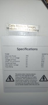
The 'Maximum Series Fuse Rating' is a bit of an enigma and is only really relevant for big PV arrays e.g. >1,000W.
Under normal operation a PV panel can only generate Isc, that's it, even if you short the output terminals together and shout at the Gods for more sunlight, only Isc will flow ... no more. Therefore, so long as you spec your PV cable ampacity for more than Isc, what does it matter if there is a short circuit? It doesn't, and that's why I never bother fusing smaller PV arrays i.e. <1,000W. Yes, of course, you're not going to get any power out of your array if there is a short ... but, critically, it won't be unsafe.
Now there is a small possibility of certain fault conditions causing a back-feeding effect when you have a large PV array e.g. >1,000W so in that case, yes, I would connect all my panels into a combiner box and, yes, under those specific circumstances, I would ensure a fuse was fitted that was below this 'Maximum Series Fuse Rating'.
Aside from that, this specification can be largely ignored, imho.
Edit: Corrected typo.