diy solar

diy solar

Modify Shunt Readings

JeromeS13

New Member
Joined
Jun 13, 2022
Messages
87
TL/DR: Is there a way to make a shunt read 1/3 of the current passing through it?

Background: I have a van with a control system with an integrated shunt and EMS. The system is hard programmed for 200AH of LiFePO4. I've upgraded to 600AH. The manufacturer says they will not support reprogramming of the system to factor in the larger battery bank. When the system consumes 200AH of capacity, the EMS will prevent usage of certain 120VAC outlets, as well as some functions of the 12VDC systems. Is there a practical way of modifying the shunt and/or wiring to make the shunt read 1/3 of the current, effectively tricking the system into thinking it still has a 200AH capacity, when it actually has the 600AH? Thank you in advance!
 
We might need a little more detail on the shunt.
The ones I’m familiar with actually measure voltage differences and infer current from that based on a known resistance for the shunt. If you can calibrate that resistance, you could just lie and tell it that the resistance is 1/3 of the actual value and it would report 1/3 of the current for the same voltage drop.
If you can’t calibrate it, the only other thing I could think to do is actually reduce the resistance by a third. But I don’t have a practical way to do that with any accuracy. A very blunt method would be to short the two terminals of the shunt, but the resistance change would likely be too small for your needs.
Note that the above all assumes that your shunt operates like (e.g.) a Victron BMV or smartshunt; a big conductor block with a less conductive part in the middle.
 
Most shunts have SOME adjustability to fine tune their accuracy but not 1/3rd of actual. A bypass could be fabricated and it must have less resistance than the shunt itself (heavier conductor). You could keep this in mind or use an internal resistance meter to measure the shunt’s value to get you in the ballpark. Potentially making it out of a copper or aluminum plate in the shape of a letter “C” with holes at each end to mount over the shunts terminals possibly sandwiching the cable lugs. Rough tuning of the bypass could be done by progressively cutting a slot across the width. Fine tuning could use the shunts software. I be thinking about fabricating it from a length of 1/4” thick 2” wide aluminum being sure to remove the oxides from the mounting area and anti oxidant purchased from a big box store.
How linear the measurement would be may be the question.
 
I do like the idea of adding two more shunts in parallel. This system has ZERO adjustability for the shunt settings, hence my dilemma. I'll look to see if I can find more information on my current shunt. Thanks guys!
 
TL/DR: Is there a way to make a shunt read 1/3 of the current passing through it?

Background: I have a van with a control system with an integrated shunt and EMS. The system is hard programmed for 200AH of LiFePO4. I've upgraded to 600AH. The manufacturer says they will not support reprogramming of the system to factor in the larger battery bank. When the system consumes 200AH of capacity, the EMS will prevent usage of certain 120VAC outlets, as well as some functions of the 12VDC systems. Is there a practical way of modifying the shunt and/or wiring to make the shunt read 1/3 of the current, effectively tricking the system into thinking it still has a 200AH capacity, when it actually has the 600AH? Thank you in advance!
That is not directly linked to the battery capacity. If you put 600Ah to the actual system, the battery will just charge/discharge slower.
That is safe with the actual shunt.
What you seem to want, is the ability to pull or push more instant current (A, not Ah) from the battery, are you?
he EMS will prevent usage of certain 120VAC outlets
But that is dangerous. The inverters ant the rest of the circuitry are tailored for a certain max current that you should not exceed.
Regarding charging: same picture you will not push more current from the panels, just charge slower.
I would not fiddle with the shunts, you may overload your installation
 
That is not directly linked to the battery capacity. If you put 600Ah to the actual system, the battery will just charge/discharge slower.
That is safe with the actual shunt.
What you seem to want, is the ability to pull or push more instant current (A, not Ah) from the battery, are you?

But that is dangerous. The inverters ant the rest of the circuitry are tailored for a certain max current that you should not exceed.
Regarding charging: same picture you will not push more current from the panels, just charge slower.
I would not fiddle with the shunts, you may overload your installation

No, that is not what I'm trying to do. I am not changing any loads at all. I have simply increased the bank size to 600AH and want my system to read the SOC% correctly.
 
No, that is not what I'm trying to do. I am not changing any loads at all. I have simply increased the bank size to 600AH and want my system to read the SOC% correctly.
But if you fiddle with the shunts, it will change much more than only the SOC.
Is your SOC coulomb-counting or voltage based?
 
But if you fiddle with the shunts, it will change much more than only the SOC.
Is your SOC coulomb-counting or voltage based?
It's definitely not voltage based. I'm not concerned with the realtime current reading. I just need to trick the system into calculating a more accurate SOC%. I have a Victron Smartshunt for actual values.
 
It's definitely not voltage based. I'm not concerned with the realtime current reading. I just need to trick the system into calculating a more accurate SOC%. I have a Victron Smartshunt for actual values.
Y'm afraid, you will not get to your target upon fiddling with the shunt.
It will fool all other current related functions of your SCC as well and these are safety relevant too.
 
Safety limitations, bulk charge (in that case not harmful), and -you told it yourself- limit for the inverter on certain sockets.
The system has a separate "shunt" for the AC current readings, which are the previously mentioned sockets.
 
Ok, do what you want. There is a folder for blue smoke reports, i hope not to see you there.
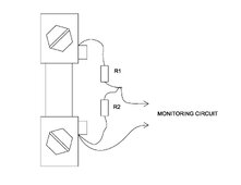
By the way: the solution from tint with the resistor bridge is elegant enough. Just use low value resistors (e.g. 1Ω) and put the common at the right side.
P.S. The right side is where the thick cable goes to your system.
I would use 3 pieces of 1Ω resistors from the same batch. that makes a perfect 1:3 divisor.
And of course you will read a correct SOC but get wrong (1/3) currents / power / efficiency readings everywhere.
 
Last edited:
Back
Top