diy solar

diy solar

MPPT “overclocking”

Chris42404

New Member
Joined
Aug 5, 2020
Messages
7
What are your guys’ thoughts on overpaneling or “overclocking” a good quality MPPT controller? I typically work with Outback, Midnite and Magnum MPPT controllers and have often thought: would slightly overloading a controller with more solar wattage help ensure that the controller can constantly output maximum power? For example, a Magnum PT100 can handle 2400w at 24v nominal. Would it be worthwhile to throw, say, 2800w of panels at it, to try and compensate for losses from things like sub optimal sun, shading, bad panel angle, etc.? More of an academic thought as opposed to something I would officially recommend
 
Kisae talk about this in their DMT1250 manual

See attached screenshot

The charger limits the input current of CH2 to 30A maximum. If a 12V solar panel is used, the maximum solar input power is around 500W. You can however “overdrive” the MPPT controller. Please note that doing this is partially an economic decision. You can install more power than the controller can use and this will contribute to better power availability. KISAE suggests a total maximum overdrive of 20% (total 600w). The extra solar panel power can compensate for cloudy (or intermittent sunny) days and around the dawn and sunset of all the days, so as to harvest more solar energy.

from https://www.kisaepower.com/wp-conte...nual_DMT12V_24V-Series_Rev-D_190612_Print.pdf
 

Attachments

  • 7106D06A-F88B-4EB7-88FA-919D7BBCCAF7.jpeg
    7106D06A-F88B-4EB7-88FA-919D7BBCCAF7.jpeg
    50.6 KB · Views: 16
It's common enough. The main point being that you pay attention to the absolute max current input spec for the controller and fuse below that to ensure that if something goes wrong in the controller things don't get out of hand. Victron specifies the normal maximum current and the absolute 'here there be dragons' current.

My own Victron has more wattage available on it's input than it can provide in terms of amps to the load but the PV current falls below even it's normal maximum so no special precautions on the PV side needed in that instance.
 
I "over paneled" my 30 amp PWM controller to 640 watts. The instructions say "up to 45 Amps" It's nice to see charging "before" sun up.
I did it for the bad days.
 
It's common enough. The main point being that you pay attention to the absolute max current input spec for the controller and fuse below that to ensure that if something goes wrong in the controller things don't get out of hand. Victron specifies the normal maximum current and the absolute 'here there be dragons' current.

My own Victron has more wattage available on it's input than it can provide in terms of amps to the load but the PV current falls below even it's normal maximum so no special precautions on the PV side needed in that instance.
Makes good sense. I’ve personally not been a big fan of Victron controllers because they seemed to under size their battery cable connection points. I’ve seen guys have a lot of problems with them overheating. May just because nobody torque specs the lugs, but better safe than sorry IMHO.

I’ve always spec’d out my builds with an oversized charge controller. All the better to add more solar wattage later if a customer wants. The Outback FM60 have been pretty well bulletproof for me
 
Getting a bunch of quotes for my Solar System at my home at the moment.

With MPPT Microinverters, So the enphase IQ7 have like 290watt rated - but most of the Solar firms are overpaneling them with 320w or up to 340w panels.

Stating that the panels only rarely get up to their rated capacity. So yes it's done.
 
Topic was recently discussed on another thread; might want to review the discussion.

 
Here’s another thought on a similar vein. What about having a system that monitors the output power of a charge controller and actively adds on more panels via relays if there is spare output capacity available. Then if the output of the controller is pegged, drop out panels to keep the charge controller at, say, 90% output
 
Here’s another thought on a similar vein. What about having a system that monitors the output power of a charge controller and actively adds on more panels via relays if there is spare output capacity available. Then if the output of the controller is pegged, drop out panels to keep the charge controller at, say, 90% output

No doubt you could make it work but suspect that in terms of cost and reliability would be better to add an additional MPPT to your system.
 
Here’s another thought on a similar vein. What about having a system that monitors the output power of a charge controller and actively adds on more panels via relays if there is spare output capacity available. Then if the output of the controller is pegged, drop out panels to keep the charge controller at, say, 90% output

It could be done, but I don’t see a reason when over paneling causes no harm to the charge controller.
I’ve over paneled several EPever tracer co trollers, manual states you can do 2 or 3 times listed output (can’t remember exactly you). I have one running at 280watts over and another at 300. Both are running 24/7.
 
I get the concept of over-paneling, and I plan to do this myself... by about 2.4% - simply because I don't want to buy a 2nd charge controller for that 140W.

For me, if it was a significant amount, I would find myself staring longingly at the panels forlorn in my decision to not have more SCC than panels - leaving sun-juice on the table every day.
 
Here’s another thought on a similar vein. What about having a system that monitors the output power of a charge controller and actively adds on more panels via relays if there is spare output capacity available. Then if the output of the controller is pegged, drop out panels to keep the charge controller at, say, 90% output

Charge controllers are getting so cheap these days. I don't see a reason to buy error prone relays. You can have multiple charge controllers,

Even if you have a few panels on one SCC and only one panel at another controller.

In an off grid scenario, I would actually build everything with redundancy. So a System like yours, I would build with 2X 1200-1500W charge controllers instead of one. Split the solar array in two locations.

Having more MPPT trackers actually increases the efficiency.

What battery are you planning?
 
Here’s another thought on a similar vein. What about having a system that monitors the output power of a charge controller and actively adds on more panels via relays if there is spare output capacity available. Then if the output of the controller is pegged, drop out panels to keep the charge controller at, say, 90% output
That's what I did, though in a more low-budget, hillbilly way. I've got two systems, for two different building, about 150' apart. In the combiner box of system #2, I rigged a splitter that can divert power from array #1 over to my main cabin. Array one feeds breaker #1 and also breaker #3 in my combiner box. Breaker #3 directs array 1 power over to system #1 in the cabin instead of system 2 by opening breaker #1 and closing breaker #3, I can send an extra 1000W over to the cabin early in the morning if I want to start my well pump at 7am. I simply have to walk 150 feet to flip breakers. It works!
 
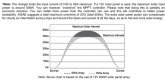
IMHO, as long as you stay comfortably within the specs of your solar controller, "over paneling" has only one significant downside and that is wasted potential energy. The good news is you don't waste much energy and you waste it only on the best "solar" days. Those days might be a concern if one is running A/C from solar but not for the rest of us. If you have a spreadsheet program (Google Sheets or Excel) and want to know how much energy is being wasted, go to the National Renewable Energy Lab's website and run their PVWatts model. Input your data and download the hourly file and plot the summer (June mostly) days when clipping will occur. The clipping is evident. If you wish, make runs with a full size controller and a smaller controller and compare them. You will see results like this plot of hourly Watthours ........ This is a fairly extreme case, a 1000W array that could do 820W but is limited to 720W by clipping. The over paneling in this case was 40 or 50% IIRC. On a rare day when the array could otherwise be doing 900W, the loss would be greater but this might happen only on a few days in June.
Example of Clipping.JPG

NREL PVWatts Calculator

Data you enter ......................
Location: enter a location where you camp
DC System Size (kW): your panel total Watt/1000
Module Type: usually premium (~20% efficiency)
Array Type: enter yours, mine is fixed roof
System Losses (%): I use 7%, includes those relevant to RVs
Tilt (deg): usually zero
Azimuth (deg): relevant only if next above is not zero
DC to AC Size Ratio: For us this is the panel array to Controller output limit
Inverter Efficiency (%): 96% is typical for 12V, use 97% for 24V
Ground Coverage Ratio: 0.4

Scroll down the page a bit and click on the hourly download option.

PVWatts gives you monthly energy loss due to clipping without the download, but that's not very useful to us because we are interested in specific low-solar days and similar; i.e., inclement weather days. PVWatts output is "statistically representative" so shows representative weather effects for each location.
 
A well designed charger will be both current and thermal limited. If your goal is to run it at max power, be sure to keep it cool. This might mean adding fans.
 
A well designed charger will be both current and thermal limited. If your goal is to run it at max power, be sure to keep it cool. This might mean adding fans.

Question. A "40 Amp" solar controller might show "520 Watts" output in the specs. 520 W would be 40 amps at 13 V. Is such a controller limited to 40 amps or 520 W when the battery voltage hits, say, 14.0 volts on the way to being fully charged? A 40 amp rating would suggest 560 W at 14.0 V. A 520 W rating would suggest 37.1 amps at 14.0 volts. Which is it? I've never loaded my solar controller high enough to see it limit.

My instinct is that that 40 amps is the determining specification. Any other thoughts?

Another question, it seems that the input clipping should occur when the input power is higher than the output power by the amount of the losses. I.e., for 96% efficiency, clipping should start at 542 W with 520 W output (520/0.96).

This may seem like splitting hairs, but it looms significant when looking at "over paneling."
 
I'm quite overpaneled, by design. I built my solar arrays on rotating ground mounts, so I can point the panels towards the sun in the mornings, and late afternoons. I have been very, very happy with the performance of my systems.
I'm considering this too.
Have a photo by chance?
 
Question. A "40 Amp" solar controller might show "520 Watts" output in the specs. 520 W would be 40 amps at 13 V. Is such a controller limited to 40 amps or 520 W when the battery voltage hits, say, 14.0 volts on the way to being fully charged? A 40 amp rating would suggest 560 W at 14.0 V. A 520 W rating would suggest 37.1 amps at 14.0 volts. Which is it? I've never loaded my solar controller high enough to see it limit.

My instinct is that that 40 amps is the determining specification. Any other thoughts?

Another question, it seems that the input clipping should occur when the input power is higher than the output power by the amount of the losses. I.e., for 96% efficiency, clipping should start at 542 W with 520 W output (520/0.96).

This may seem like splitting hairs, but it looms significant when looking at "over paneling."
I can't answer your question specifically but from the standpoint of "design", power is a function of current and voltage. But in real life, current=heat for any given circuit. So often people will work toward current limit or a current level. It is pretty easy to detect a current level with a Hall sensor or a shunt.

In today's designs, a micro computer inside the device is very common. If you have a micro that can already monitor the voltage and the current for other reasons (like to display them) then it is just a little program code to figure "power" and power limit the output. But in the end, current = heat, so why bother. The goal is to "don't let the smoke out", so just limits are set to avoid excess heating, more than getting the last few watts to pass to the battery. Just my thoughts.

I think that's got to be close. The solid state switching devices that generate the output are generating less heat when the input and output voltage are closer to the same since the current spans a lower voltage. I..e., lower the solar controller input voltage or raise the output voltage and the solar controller losses are lower (this is evident in the loss curves in my solar controller manual). That would suggest higher output Watts at higher output voltage. Or, the same current with higher voltage means more Watts. I'm going to go about 25% above my solar controller ratings with more panels next year, maybe I'll get a chance to really test this .... on a good sunny day.
 
Back
Top