diy solar

diy solar

MPPT off road set up?

RobbieD

New Member
Joined
Nov 20, 2019
Messages
34
Hi, 1st post. Love the YouTube videos. Will is an absolute legend. I do a fair bit of of road camping out of my 4X4. Im adding a roof top tent and upgrading the current solar set up. Need a little guidance. Here Goes:

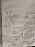
current set up: 60watt panel on roof feeding to a basic solar regulator. Hooked up to the cars start battery, smart alternator in the car with a diode fuse which tricks the alternator to pump out 14.7 volts. From start batt, a 25amp DCDC charger through to my 100AH AGM auxiliary battery. This is all under the hood in the engine bay. And works well. Large cables running from the Auxiliary battery to the rear of the wagon. Connected to a fuse distribution box with 8 ports, 10 to 15amp fuses for various camp lights, 40ltr Engle fridge, USB and cig charger ports. Fridge is on 24/7, system has been running faultlessly for 2.5 years......but I wish to run a 2000w inverter for coffee machine and makita tool dual battery charger for work....... So:
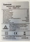
275kw solar panel on roof top tent., want to run a victron 100/20 in place of the basic regulator. Keeping the DCDC charger and the wiring to the rear as is but adding solid terminals for the new inverter to connect to.

the questions I have are:
1. Can the victron 100/20 be mounted under the hood in the engine bay? Waterproof, Heat issues etc?
2. On the VicTron 100/20 it has Load terminals. If I connect these terminals to the roof top tent, will it provide power for the RTT at night from the auxiliary battery or power only when sun is shining?
3. Will it be an issue having the inverter 5meters away from the actual battery? Cables are 4 or 6 gauge, can’t remember, will have to check.
4. If point 3 is an issue what are the options? I can’t shift battery to rear and am really struggling with GVM limits so I don’t want to add a 3rd battery.
5. Due to said weight issues,the system needs to be able to accommodate lithium battery upgrade once the current batteries die.
Thanks so much, in advance for advice forth coming.
OH yeah , from West Lakes in South Australia
 
1. The Victron does have a working temperature range. The full rating temperature is up to 40c. At that point the unit reduces its output to protect itself. Maximum temperature is 60c. Putting it in a hot engine bay won't kill it, but you will be reducing the power from it.

2. Yes, the load output will take power from the battery. The maximum current from the load output is 20 amps, it means it. The Victron charge controllers respond to even short over current situations so if you are connecting a load with a high inrush current odds on the Victron will trip its output.

3. If its a 12 volt system you do have to use heavy cables to avoid voltage drop at the inverter's DC input as you don't have much headroom to play with. 1.5 volt drop could push your inverter into low voltage shutdown. You will be pulling about 180 amps with the battery at 11.5v with the inverter at full tilt. The inverter may have a low voltage cut off at 10.5v so you can see there's really no room to play with. Half a volt drop at 180 amps over 5 metres means you will need to use 2 gauge wire, and this assumes you have a really good chassis return for the - side. The shorter the wire length the better. This assumes that you will be running the battery down a fair way. If the voltage stays up at 12.5 volts under full load that's 160 amps which gives you some more breathing space but 2 gauge is still warranted IMO.

4. If you can't shorten the wires or use 1 gauge or double up cables and do need that full 2kW from the inverter you might have to consider moving to a 24v system.

See if someone else on the forum can come up with some advice before setting up.
 
1. The Victron does have a working temperature range. The full rating temperature is up to 40c. At that point the unit reduces its output to protect itself. Maximum temperature is 60c. Putting it in a hot engine bay won't kill it, but you will be reducing the power from it.
- Hmm ok, would would be better suited to the engine bay area?

2. Yes, the load output will take power from the battery. The maximum current from the load output is 20 amps, it means it. The Victron charge controllers respond to even short over current situations so if you are connecting a load with a high inrush current odds on the Victron will trip its output.
-Thank you, same as 1., what’s a better option?

3. If its a 12 volt system you do have to use heavy cables to avoid voltage drop at the inverter's DC input as you don't have much headroom to play with. 1.5 volt drop could push your inverter into low voltage shutdown. You will be pulling about 180 amps with the battery at 11.5v with the inverter at full tilt. The inverter may have a low voltage cut off at 10.5v so you can see there's really no room to play with. Half a volt drop at 180 amps over 5 metres means you will need to use 2 gauge wire, and this assumes you have a really good chassis return for the - side. The shorter the wire length the better. This assumes that you will be running the battery down a fair way. If the voltage stays up at 12.5 volts under full load that's 160 amps which gives you some more breathing space but 2 gauge is still warranted IMO. - Yes the inverter does pose all of the issues. Might have to start drinking tea.... I assume reducing to a 1500w PSW will help in the capacity side of things? Current setup with fridge never drops below 12.6. No inverter..

4. If you can't shorten the wires or use 1 gauge or double up cables and do need that full 2kW from the inverter you might have to consider moving to a 24v system. Hmmm maybe in the next rig, everything in this one is already 12v

See if someone else on the forum can come up with some advice before setting up.
Thank you so much! Appreciate your time.
 
After some thinking about the info you have provided, and checking availability and cost of wire. I can run 00AWG from battery to a rear buss bar, manual rear 150amp breaker. Then mount victron 100/30 in rear of car, then connect victron, inverter and fuse block to the buss bar, each with its own manual breaker.

can you seen any issues with running it this way? Hope my stick drawing makes some shot of sense to you. Thanks again.
 

Attachments

  • image.jpg
    image.jpg
    124.4 KB · Views: 14
If 0 gauge is possible that would certainly take care of the voltage drop problem. Although it's probably just how you've drawn it, that buss bar is two separate bars, one for + one for -, and the - from the Victron is just not shown for convenience?

The only thing that I can think of would be a way to disconnect the solar panel without arcing. If you are happy with covering the panel up when disconnecting it, that's fine. The panel would be a 24v model (VoC somewhere around 36 volts)?

Just in case see if anyone else comments, it's always good to have another set of eyes looking at things.
 
Correct, I haven’t drawn in the - on a few of them, trying to keep it neat.

Im assuming the 0 gauge Cables work both ways? As in, power from battery front to back and solar charging from victron in the rear of car charging to the battery?
 
Re removing panels I will have a 50amp Anderson connection at the panel connection, will this suffice? panel is 36v.
 
Yes, the Victron will be able to charge the battery. There won't be much voltage drop (tens of millivolts) across that cable with the sort of current the Victron will be providing so it should be a case of plug and play. If you want to the Victron does have a programmable voltage offset to help account for drop across the cable when it is charging the battery.
 
This is the panel details
 

Attachments

  • ED1DA4D0-0494-49DC-B1FE-D2C075B5417F.jpeg
    ED1DA4D0-0494-49DC-B1FE-D2C075B5417F.jpeg
    142.2 KB · Views: 2
Re removing panels I will have a 50amp Anderson connection at the panel connection, will this suffice? panel is 36v.
The pins in the connector will get arc damage, but if it's only being disconnected once in a blue moon that isn't going to be a problem.
 
Back
Top