diy solar

diy solar

MRBF fuses - OK for 48V LiFePO4system?

Unfortunately not - the Lynx Distributor has 8mm bolts on 51mm centres and only handles Mega fuses. I'm resorting to mounting a Midi fuse outside the Lynx. It would have been nice if the Distributor used some kind of insert fuse holder that was swappable to hold different format fuses. Maybe for Victron's next version of the product. :)
This forum willprobably yell at me for this:

I ended up doing 1 mega fuse (200a) for my 48v system (the one you linked actually) in the lynx for the inverter.

Then I did 2 circuit breakers (gasp!) for the DC distro and DC airconditioner.

Additionally there is 1 class T fuse @ the battery positive terminal + 6 inches.

I'd have loved 3 mega fuses in the lynxx rather than 1 + 2 CBs, but I couldnt find any 58V fuses small enough for my DC distro + AC (~30/40Amps)
 
I looking to build a 48V system, 4p16s LiFePo4 within the next several months. I haven’t been on this form doing my due diligence and research. I see a lot of discussion about fusing between battery banks and the inverter. Using Sol-Ark12K inverter.
Is anyone willing to show some photos or have diagrams of how their battery systems are built with fuses/breakers/switches, I’d like to see how this is done? I have also seen some discussion about circuit breakers and/or 48v disconnect switch between the battery bank and inverter as well. Also curious if so and how folks are "grounding" large battery packs? Grounding rods like a normal 200-Amp AC panel would be grounded?

Looking for others experience here.
Thanks
 
Last edited:
Here's a close-up showing copper busbar for negative, two class T fuses connected to positive by a pair of 4/0 cables.
I have one string of AGM batteries fanning out to four inverters; two inverters (each has its own breaker) connect to each fuse.


My inverter brand doesn't recommend grounding 48V battery, but says either negative or positive can be grounded, in which case a ground wire needs to go from that to a large ground terminal in the inverter (so if cable shorts to enclosure of inverter it has a good path back, doesn't put battery current through some other small ground wire.)
So a class T fuse on the positive cables close to the battery positive terminal between batteries and Sol-Ark which is a 48v system. I'll have 1120 Ah (58V max) in my battery pack. I'll be using 4/0 welding cable, so what size class T fuse is recommended for that amount of AH?
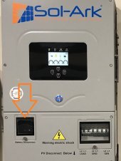
Also my Sol-Arks have a breaker disconnect switch built in where the battery cables connect to the inverter. So, I'm thinking that I wouldn't need another point of disconnect (breaker or otherwise) between the batteries and Sol-Ark...? (see photo)

SolArkPict.jpeg
 
4/0 with 90 degree insulation in a bundle of up to 3 current-carrying conductors is good for 260A according to NEC.
Single conductors in free air, good for 405A.

I think Sol-Ark is 9000W, even if battery is as low as 42V, 214A for 100% efficiency. Divide that by inverter efficiency, multiply for 1.25 margin to avoid nuisance trips. My latest advice (as of some math I did this morning) is multiply by another factor of 1.12 because current draw from battery isn't really DC, it has a huge ripple.

Assuming 90% efficient inverter, want 333A fuse, round up to 350A. So I think that's a good value (or 400A), just keep 4/0 cables exposed for good airflow.

The switch you've got is good enough. Fuse at battery protects against shorts in cable, breaker protects against overload and provides disconnect.

1120 Ah - is that LA or lithium? How many battery strings in parallel?
If lithium, is that 16s3p or 3p16s?
I think each string can deliver something like 20,000A into a short circuit. If 16s3p, you could use three fuses, one per string. Class T is rated to interrupt 20,000A but not the 60,000A I think you can get with 3 parallel strings.

There are some other fuses with 50,000 AIC rating you might consider. I have one from Feraz-Shawmut.
 
Very good info!! I thought the built in circuit breaker "battery disconnect" would be good by itself. Yes, i was thinking a 400amp class T fuse would be the my choice. My inverter is rated as 96% efficient, per Sol-Ark manual.
My 4/0 cables will be free air from the battery up to where they enter my wiring trough, but they will not be bundled at anytime.
1120 Ah LiFePo4, doing a 4p16s layout. 280 ah each cell.
I'll need to check into those Feraz-Shawmut fuses.
 
That's probably 96% peak efficiency at optimal battery voltage if the moon and stars line up.
Do they publish a curve of efficiency vs. wattage? Family of curves for different battery voltage?

How long in the wiring trough? If more than 2', derating is supposed to be based on that environment.
Is your wire 90 degree C, or 105 degree C? (of course, other wires in the trough will suffer its heating.)

Not sure if code supports it, but my way of thinking is breaker at the far end protects against overload. Even if wire ampacity is lower than near-end fuse rating, if wire is large enough to be the ground wire for a circuit with that fuse, it will hold up long enough to blow the fuse in case of a dead short.

I think your battery can deliver up to 80,000A. You could do some math on the cable resistance, see how much that reduces current for a loop to the first plausible location of a short.

There are longer class-T fuses rated for 600VDC, but the same 20,000 AIC. Shame they don't offer a range of AIC depending on voltage.
The Feraz-Shawmut fuse I have is fast blow semiconductor (i.e. to protect one) fuse, 250A, 50,000 AIC.
Ideally fuses are dual element - fast blow fuse way higher than wire ampacity, to protect in case of a short. Also slow-blow at desired rating for wire ampacity. By using fuse and breaker, I try to divide the job between them. Fuse because it has the higher AIC.

Here's one. $157, 400A, AIC "Breakthrough Current" 100,000A at 250VDC
I guess that's cheaper than four Class-T fuses.
I'm not finding a fuse holder rated above 200A, though.


Make sure your busbars have good contact. One guy splattered a busbar without blowing the fuse.
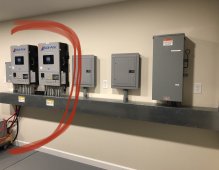
The 4/0 welding cable says 105°C on the side. For the main inverter, the welding cable from where it enters the wiring trough until it enters the inverter is approximately 12 to 15”. For inverter number two that distance is probably 24 to 30”. See photo. B4B0AB2C-2865-481F-A202-19A374197460.jpeg
I will use a 400 amp class T fuse on my positive battery connections at the battery. Today, I was able to speak with technical support at Sol-Ark. I was told that each battery cable disconnect breaker located inside the inverter is capable of handling 250A each.
However my max charge and discharge current that is allowed by the Sol-Ark is only 185 A each inverter. (370 amps total) So based on that information, I do believe that the battery cable disconnect breaker will trip if needed. I believe that the 400 amp fuse would handle a battery short circuit.
So, I will use the class T fuse but will not install an additional circuit interrupter and allow the battery cable disconnect breaker to perform that duty as prescribed per Sol-Ark.
Yes, I’ve been reading a lot about bus bar connection and the amount of torque needed to make a good connection. I ordered a inch pound/nano meter torque wrench to help with that.
I will check out the link you posted in your reply above. Thanks for the information and I’m going to look into that.
 
The higher ampacity of 105 degree C and short run in cable tray should take care of that.
I would suggest strapping any conventional wires such that they can't touch these hotter cables.
(And then of course the inverter breakers protect cables to lower current, lower temperature.)

Is that a separate 400A fuse per inverter?
I use one 350A class T per two inverters.

For yours, my concern is how high the short circuit current can be from the 4p battery. Four times what Class T is rated, I think.
Are your BMS/disconnect and busbar array able to handle 500A from two inverters?

I've imagined thermistors stuck to all busbars to detect hot spots and shut down system.
 
I'm thinking of doing a 350amp class T for each inverter (still researching) but maybe 200 amp class T per inverter would be enough since my max charge/discharge rate is 185amps per Sol-Ark...that way I've got a fuse in each of my 2 positive cables.
370 max amps is all both inverters will draw according to Sol-Ark tech support today. Thinking of using 4/0 welding cables instead of "busbars" on my battery packs?? This way, if the batteries swell a bit and "flex" during charge/discharge, I'm not worried about strain on the m-6 terminals and may handle the amps better than thin bus bars....?
I am planning in using a Batrium or Orion BMS, not sure yet. The Orion will actually commnicate with Sol-Ark through CANbus where the Batrium can not communicate with Sol-Ark at all..
 
I think you want the fuse trip-curve coordinated so breaker goes first, except in a short. Fuse curves are published, don't know if you can get model/data for breaker in the inverter.

Various ways of thinking on busbars. My AGM batteries have copper, bronze, brass, or something like that, so cables makes sense. Only 8, 6V batteries to connect.

Your aluminum terminals were supposed to be welded to busbars. I've seen some busbars with a bend so they can flex. You'll need to deal with metals and whatever other issues. 4p16s is a LOT of cables. I guess that's cheaper than 4 BMS and half the cables.

The busbars seem undersize, but I think they stay cool by dumping their heat into the battery. 2 x 185A / 4 = 92A per busbar. (unless one has bad contact and current goes through others.)
Well that makes sense on the fuses. Maybe I should get a higher amp fuse, one each positive cable, between the inverter and battery, that can handle just the short circuit. Breaker will trip for anything else below, let’s say 350 amps, if that’s the fuse I used.
My original thought is that the standard busbars would handle the parallel connection, but I would use the 4/0 welding cable for all series connections. If for some reason a single bus bar wasn’t enough, I will have enough extra bus bars to double the bus bars up for the parallel connections, but think that is not needed. However I’ve been reading a lot of threads and have actually seen a couple photos where batteries are charged, they do tend to expand slightly. Therefore I was considering using 4/0 welding cable for both parallel and series connections, just to help with that stress?
The batteries I have ordered, do have welded M6 studs on the terminal.
I know that making all the connections out of 4/0 welding cable can get a little expensive and time consuming. But it may be worth the extra time and expense just to hopefully prevent any issue with the flex over the years of charging and discharging the batteries.
I do not plan to charge my battery up to the full 3.65 V, more in the 3.45-3.5v range. If my batteries are 1120ah, and I can only max charge at 370 amp, that’s only .33 c rating max anyway, correct? So maybe I won’t get a lot of battery swell charging at that rate?
 
I've never worked with LiFePO4, but from what I gather here it is SoC not charge rate that produces the swelling.
You can compress the cells in the series stack, have a gap in the parallel direction so busbars should be fine there.

If busbars had an arch or an omega shape, that would provide compliance. If you try to bend metal, especially aluminum, there is a concern about cracks.

Some guys have used cables, some used busbars. Either way, need to get rid of oxide from aluminum surface and protect it. Some guys got hot terminals in discharge. Some top-balanced and ended up with a low cell (but it came up with additional charging.)

Welded studs is good since you can have a lot more torque. (counter that with busbar or cable, not cell terminal, since terminals apparently have an 8 Nm spec for resisting turning.)

0.33C charge rate - set low-temperature disconnect high enough to tolerate that.
 
Back
Top