diy solar

diy solar

Multiple Charge Controllers to deal with different battery chemistry

Zakkieboy44

New Member
Joined
Apr 6, 2023
Messages
6
Location
Kettering
I think I have an idea on how to charge some spare Lead Acids along side my (new) setup but lack the expertise to know what components I'm talking about, so please bear with me whilst I explain my theory and get some wording wrong!

After reading that you shouldn't really mix battery types, and having a spare (nasty) charge controller I thought this route would work, as each controller is responsible for its own battery array. (1 x Lifepo4, 2 x Lead acid) -12v

My logic however is questioning the flow down into a single invertor - as I don't want any form of backflow from one battery to another, and after looking at blocking diodes there doesn't seem to be a 'consumer friendly' way to implement into the setup and im not 100% sure its the right tool for the job

I tried to draw a simplified layout, and would welcome any thoughts or feedback on the plan, and indeed what the names are of the 'bits' in the green circles that I would need to make this work - safely. (The picture doesn't show the fuses on the connections to the invertor)
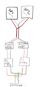
solar2.png

Id appreciate any feedback, however short - I have searched for a similar setup/situation, but my google skills seem to be failing me!

Thanks

Zak
 
Ditch (recycle) the lead side of the schematic. Then it will all make sense. Never going to work right combining these different chemistries.
 
Max charging voltage for a lithium battery is 14.5 volts. Max charging for a temperature compensated lead acid battery is in excess of 15 volts. In your diagram, the batteries are shorted together and will exceed max lithium volts. At that point, the battery gets damaged or the BMS shuts off

Two ways that you could use the lead acid batteries in your system, and neither I recommend

1) charge batteries with a single SCC to a voltage. Less than the lithiums can take. This will keep the lead acid batteries permenantly at a lower SOC, which is not good. Others have done this rarely, and one or two has spoken well about results. Except in an experimental sense to see how this is done, I see no efficiencies.

2). Hook a SCC to the LITHIUM, and create a second circuit with a DC to DC charger hooked to the lead acid batteries to run select DC items. This is a lot of work and some expense, which I don’t see being worth the cost and effort.

The lithiums together with lead acid is like chasing unicorns.
 
Last edited:
Ditch (recycle) the lead side of the schematic. Then it will all make sense. Never going to work right combining these different chemistries.
Thats the bit I'm trying to avoid - plus the extra 30ah will come in handy (for free) as the raspberry Pi im using for monitoring is chewing through more than expected :(
hmmm, unless I run the Lead acids on its own panel just for the rPi4...

Thanks for the new thought pattern!
 
Max charging voltage for a lithium battery is 14.5 volts. Max charging for a temperature compensated lead acid battery is in excess of 15 volts. In your diagram, the batteries are shorted together and will exceed max lithium volts. At that point, the battery gets damaged or the BMS shuts off

The lithiums together with lead acid is like chasing unicorns.

Who's doesn't want to capture a unicorn? :ROFLMAO:

I get your logic about charging rate, which is why I was thinking about a blocking diode (link) inline on each feed from the battery to the inverter. To stop any of the other batteries voltage reaching the other battery - isolated somewhat as the positive charge cannot flow backwards up the cable?

Is that not what these diodes do?
I think you are trying to use a blocking diode similar to what I mentioned a separate circuit for a battery charger.

I'd have to see a schematic or block diagram to be sure. My initial thought is that a blocking diode would not do what you want. Diodes block current from going one direction. Not usually used as will let it flow until it reaches X volts and then it shuts off. That would require circuitry for a converter or charger. A Bridge Rectifier would convert AC to DC with diodes, but I don't think this is what you're asking.

If you search on this forum you can find posts of people who have actually done mixed chemistry batteries. Trouble will be sifting through the posts about people who want to do it, who have tried it, and those who actually posted their results.
 
Thats the bit I'm trying to avoid - plus the extra 30ah will come in handy (for free) as the raspberry Pi im using for monitoring is chewing through more than expected :(
hmmm, unless I run the Lead acids on its own panel just for the rPi4...

Thanks for the new thought pattern!
Monitoring 30ah with raspberry? Free can get rather expensive. Already a second controller to save that tiny battery.
 
I think I have an idea on how to charge some spare Lead Acids along side my (new) setup but lack the expertise to know what components I'm talking about, so please bear with me whilst I explain my theory and get some wording wrong!

After reading that you shouldn't really mix battery types, and having a spare (nasty) charge controller I thought this route would work, as each controller is responsible for its own battery array. (1 x Lifepo4, 2 x Lead acid) -12v

My logic however is questioning the flow down into a single invertor - as I don't want any form of backflow from one battery to another, and after looking at blocking diodes there doesn't seem to be a 'consumer friendly' way to implement into the setup and im not 100% sure its the right tool for the job

I tried to draw a simplified layout, and would welcome any thoughts or feedback on the plan, and indeed what the names are of the 'bits' in the green circles that I would need to make this work - safely. (The picture doesn't show the fuses on the connections to the invertor)

View attachment 144259

Id appreciate any feedback, however short - I have searched for a similar setup/situation, but my google skills seem to be failing me!

Thanks

Zak


I'm not sure about 2 charge controllers drawing off the same solar array ? Does that work ??


In my mind you're simplest solution to be able to make use off all your batteries would be a DC change over switch before the inveeter , use one bank then the other.

Or failing that 2 separate systems , each with its own inverter
 
I'm not sure about 2 charge controllers drawing off the same solar array ? Does that work ??

Nope, and PWM would win as it shorts the panels to the battery. MPPT wouldn't see PV voltage high enough to start.

In my mind you're simplest solution to be able to make use off all your batteries would be a DC change over switch before the inveeter , use one bank then the other.

Or failing that 2 separate systems , each with its own inverter


Overall, I think the the diode concept would work, but they need to be carefully sized.

I don't share the same fear of paralleling PROVIDED you fuse both battery banks a common bus bar. The biggest risk is a shorted cell in the lead-acid, which would create a high deltaV between the two batteries causing the LFP to dump into the lead-acid. Fuses would prevent this.

It's worth noting that in either case, the lead acid is going to do almost nothing almost all the time. Operating voltages are such that the LFP will be nearly tapped out before the lead acid begins to deliver significant capacity.

IMHO, a better solution would be to power the system via LFP and run a float charger to keep the lead-acid floated if you ever need it as backup.

That's what I do with my 4X T-1275 Trojans (wired in parallel, 12V)... just in case my 48V NMC battery or BMS go inop.
 
Nope, and PWM would win as it shorts the panels to the battery. MPPT wouldn't see PV voltage high enough to start.

Overall, I think the the diode concept would work, but they need to be carefully sized.

I don't share the same fear of paralleling PROVIDED you fuse both battery banks a common bus bar. The biggest risk is a shorted cell in the lead-acid, which would create a high deltaV between the two batteries causing the LFP to dump into the lead-acid. Fuses would prevent this.

It's worth noting that in either case, the lead acid is going to do almost nothing almost all the time. Operating voltages are such that the LFP will be nearly tapped out before the lead acid begins to deliver significant capacity.

IMHO, a better solution would be to power the system via LFP and run a float charger to keep the lead-acid floated if you ever need it as backup.

That's what I do with my 4X T-1275 Trojans (wired in parallel, 12V)... just in case my 48V NMC battery or BMS go inop.
Some very helpful comments, Thank you - it shows its more complicated than I envisaged:

I assumed both Charge Controllers would be happy (be it, with less amp-age) - and I didnt consider my main battery higher a higher settled voltage (not that I know what it is, my EcoWorthy is unpredictable)

I don't hold the experience to size the components, so I think a second small panel with a separate inverter may be the safest route all round - or as it was mentioned earlier - recycle the batteries etc

Thanks to all that shared their experience and views!
 
I did think that, but it seemed a bit old school.... ?

It'll do! That's what I do in my shed , couple of different panels , couple of inverter, different batteries. It's only a little DIY system at the end of the day

Actually the more separate systems you've got the more redundancy, one component failing won't leave you in the dark
 
Back
Top