Hi all.
Started learning this solar business a few weeks ago.
TLDR - can I wire 2 separate transfer switches (like Reliance Controls 31406CWK) to one/same generator inlet box to power parts of both via Ecoflow Delta Pro + Extra Battery.
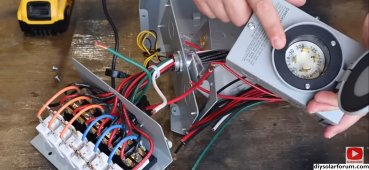
Longer version. My main electrical panel is in the back of the house and has breakers for rooms, bathrooms, heater, fridge, dish washer, washer/drier, it also has 40 amp breaker for ac and a 60 amp breaker for a garage subpanel. I connected a transfer switch to this main panel per attached pic and transferred rooms, fridge, washer/drier to it to run off Delta Pro which is charged by solar. As you can see the generator inlet is currently on this transfer switch, but I am moving it separately into the garage, about 60' run (via 6-4 wires and emt conduit) so I can move EF DP + EB also into the garage and out of the elements (transfer switch itself will stay where pictured next to main panel outside in the back of the house).
In the garage, the subpanel has breakers for microwave/oven, kitchen lights, few outlets in common area, wifi outlet, garbage disposal, few accent lights, exterior LED night lights, garage lights and outlets. I want to wire up a similar transfer switch to the garage subpanel to transfer wifi outlet, some lights and outlets to it. The transfer switch for the garage subpanel is not installed yet, as I'm researching this. And I'm wondering if I can wire that additional transfer switch for the garage subpanel into the generator inlet box that is powering the transfer switch for parts of the main panel. What I'm trying to do is transfer/power key lights and outlets from single EF DP+EB inlet in entire house, it just so happens that my house is wired in such a way that kitchen lights and other outlets are on the garage subpanel.
Additional details. I am trying to slowly move off of using electrical grid to power parts of the house "full time" from DP+EB and solar input. Lights in the house are LED, appliances are efficient (I am currently not planning on powering ac/microwave/oven, ie 240v, but might move to 2x EF DP with double voltage hub in fufure).
In my head, I think it should be doable to connect both transfer switches to the same inlet box properly crimping/pigtailing the wires and connections in the inlet box. It is not(?) different than if my main panel had all the separate breakers on it that are in the garage subpanel and I got a transfer switch that can handle 10-12 circuits? Obviously I won't be able to power everything at once, etc, etc. There might be some details that I'm missing due to the main/subpanel setup. I'm not an electrician") . Happy to learn, appreciate the help.
. Happy to learn, appreciate the help. 
What do you think?
Started learning this solar business a few weeks ago.
TLDR - can I wire 2 separate transfer switches (like Reliance Controls 31406CWK) to one/same generator inlet box to power parts of both via Ecoflow Delta Pro + Extra Battery.
Longer version. My main electrical panel is in the back of the house and has breakers for rooms, bathrooms, heater, fridge, dish washer, washer/drier, it also has 40 amp breaker for ac and a 60 amp breaker for a garage subpanel. I connected a transfer switch to this main panel per attached pic and transferred rooms, fridge, washer/drier to it to run off Delta Pro which is charged by solar. As you can see the generator inlet is currently on this transfer switch, but I am moving it separately into the garage, about 60' run (via 6-4 wires and emt conduit) so I can move EF DP + EB also into the garage and out of the elements (transfer switch itself will stay where pictured next to main panel outside in the back of the house).
In the garage, the subpanel has breakers for microwave/oven, kitchen lights, few outlets in common area, wifi outlet, garbage disposal, few accent lights, exterior LED night lights, garage lights and outlets. I want to wire up a similar transfer switch to the garage subpanel to transfer wifi outlet, some lights and outlets to it. The transfer switch for the garage subpanel is not installed yet, as I'm researching this. And I'm wondering if I can wire that additional transfer switch for the garage subpanel into the generator inlet box that is powering the transfer switch for parts of the main panel. What I'm trying to do is transfer/power key lights and outlets from single EF DP+EB inlet in entire house, it just so happens that my house is wired in such a way that kitchen lights and other outlets are on the garage subpanel.
Additional details. I am trying to slowly move off of using electrical grid to power parts of the house "full time" from DP+EB and solar input. Lights in the house are LED, appliances are efficient (I am currently not planning on powering ac/microwave/oven, ie 240v, but might move to 2x EF DP with double voltage hub in fufure).
In my head, I think it should be doable to connect both transfer switches to the same inlet box properly crimping/pigtailing the wires and connections in the inlet box. It is not(?) different than if my main panel had all the separate breakers on it that are in the garage subpanel and I got a transfer switch that can handle 10-12 circuits? Obviously I won't be able to power everything at once, etc, etc. There might be some details that I'm missing due to the main/subpanel setup. I'm not an electrician
. Happy to learn, appreciate the help. What do you think?