Hey All -
Would appreciate a gut check here. I have a 50mp interlock with 50 amp inlet already set up in my home, but I'd like to add the ability to feed into that interlock from an indoor inlet used with a battery bank/solar inverter as well, or at least have the option if needed in an emergency. I picked up a 100A/100A transfer panel for super cheap (<$70), so trying to make this work with the setup as best possible.
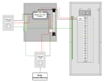
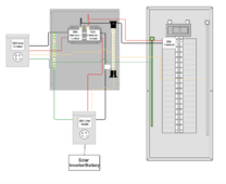
Below is the setup I'm currently looking at. Would keep the same 50A outdoor inlet on a 50A interlock breaker, add the transfer panel in between them, then on the second part add a 30A indoor inlet. Since the 50A breaker on the interlock is preventing draw beyond that from the house my understanding is the 100A transfer panel breakers should be fine, but my concern is the 30A inlet. If I can't find a compatible 30A breaker for the transfer panel should I add some sort of 30A main lug load center in between the 30A inlet and the 100A breaker on the transfer panel to ensure the inverter doesn't get too much power pulled?
Any concerns with this setup?


