diy solar

diy solar

Interlock circuit with outside inlet for generator and inside inlet for solar?

DIYSol

New Member
Joined
Oct 13, 2023
Messages
8
Location
STL
Does anyone have any good suggestions for how to have both an outdoor generator inlet and an indoor solar inlet/inverter connection tied into my interlock kit?

Currently, I have an outdoor 50A inlet, which ties in to an interlock on my panel. I would like to start experimenting with going solar purely as a form of backup to begin with, and given my basement is downstairs with no egress, would like some sort of option to be able to flip the interlock on and decide while downstairs if I use generator or solar inverter.

From what I've found, the double pole double throw manual switches that also switch the neutral are VERY expensive, on the range of $800+. An alternative seems to be an RV style ATS, which switches both L1, L2 and the neutral at an oddly reasonable price.

The questions:
  1. If the interlock kit is bonded neutral in the panel and the generator is floating (as it should be), I assume adding multiple inlets would require switching neutrals on the interlock circuit as I have outlined above? Or could I get by just using a double throw for the 2 hots and having both the inside and outside neutrals bonded at the manual transfer switch? I assume this is no go since there is a chance it backfeeds over neutral to unused inlet.
  2. Is there any good way to have the inside inlet, which goes to the interlock, also charged by a circuit on the main panel? My concern was that if i flip the interlock on and don't unplug the inverter AC input, which is fed from the panel, then there would be a full circular path, essentially solar inverter powering panel via interlock, panel then powering solar inverter via breaker. I can't think of any way to prevent this that isn't completely reliant on me knowing to turn off the AC input breaker before flipping interlock over. Unless this concern is unfounded?
Appreciate any input available!
 
From what I've found, the double pole double throw manual switches that also switch the neutral
That would be a 3 pole.
A double pole double throw, only switches L1 and L2.
Which is actually what you need. You don't want to switch the neutral. That makes it a separately derived system. And adds more complications.
 
If the interlock kit is bonded neutral in the panel and the generator is floating
Generator is not floating. And it shouldn't be.
The panel is bonded, therefore everything connected to it is bonded.
having both the inside and outside neutrals bonded at the manual transfer switch?
Do not bond N/G at the transfer switch.
Only one N/G bond should exist. This is at the panel.
Is there any good way to have the inside inlet, which goes to the interlock, also charged by a circuit on the main panel? My concern was that if i flip the interlock on and don't unplug the inverter AC input, which is fed from the panel, then there would be a full circular path, essentially solar inverter powering panel via interlock, panel then powering solar inverter via breaker. I can't think of any way to prevent this that isn't completely reliant on me knowing to turn off the AC input breaker before flipping interlock over. Unless this concern is unfounded?
You could add or make another interlock for this.
It wouldn't be hard to design a single slide bar interlock. To cover all situations.
 
3 inputs, grid + generator + inverter?
You could cascade two breaker panels with interlocks.
 
3 inputs, grid + generator + inverter?
You could cascade two breaker panels with interlocks.
I think I was assuming this would not work because the neutral for the unused inlet (whichever one is not being powered) would always be live?

Essentially, if I cascade two breaker panels with interlocks does the neutral need to be “switched” I think would be the term?
 
I setup something similar to what the OP is looking for with this: https://www.reliancecontrols.com/pr...s-manual-transfer-panel-metal-indoor-tca0505d

I have a generator inlet wired to one side, my inverter wired to the other. I can switch between either which then goes to the breakers in my sub panel with an interlock from main panel. Works great but going to be changing this up soon to have grid power or generator using this switch ->Inverter AC IN - Inverter AC OUT->breaker with interlock in sub panel. This way if grid goes down and batteries are low I can charge them from generator and power loads simply by throwing that manual reliance switch.
 
About the only time we would switch neutral is for a mobile system, like RV or boat.
When plugged in to shore power pedestal, we expect to get a neutral bonded to ground. So don't bond locally.
When power is not seen from the pedestal, maybe we are unplugged, or maybe we are still plugged in but the grid went down. Don't know, so open the neutral wire with a relay, and bond neutral to ground locally.

If you have a hard wired grid connection that provides neutral-ground bond, also a generator with neutral not bonded to ground, and an inverter with neutral not bonded to ground ... then just keep all neutrals always tied together. You can use an interlocked breaker panel (or multiple cascaded) to switch L1 and L2.

My inverter is meant for fixed installations, switches only line. Downstream of it I have two interlocked breaker panels so one, the other, or both can be fed from the inverter. Parallel not series, because I have only one source, two loads. If I added a generator it would be before the inverter.
 
I think I was assuming this would not work because the neutral for the unused inlet (whichever one is not being powered) would always be live?

Essentially, if I cascade two breaker panels with interlocks does the neutral need to be “switched” I think would be the term?
No
 
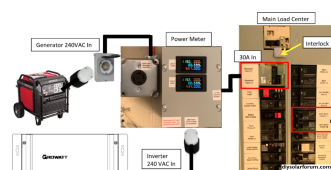
I have an interlock on the main panel connected to an indoor generator input box (with power meter) used for my battery inverter setup. I also have an outdoor generator input box that feeds a receptacle near the indoor input box. I use a short 2 ft jumper cord between the 2 if I need to feed the interlock with the generator. In most cases, we'll use the generator to power a Chargeverter that will charge the batteries directly while the inverter is powering the house.
1697324927113.png
 
Last edited:
So real question, What good is a transfer switch that switches neutral after the system bonding?
 
So real question, What good is a transfer switch that switches neutral after the system bonding?
If you switch the neutral. The second source becomes a separately derived system. It would have to have its own N/G bond. And create a new grounding system.
So, every time you switch between sources, you also switch between grounding systems.
This is common for mobile systems. But not preferred for permanent installations.
 
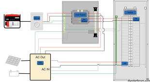
Thanks all for the input here! If I'm tracking this correctly the setup would look similar to what I've picturered below when it comes to the interlock switch portion, is that right?

Would this type of setup also work at all for how I layed out the inverter/solar as a backup option for the interlock as well? The idea would be using line to panel as normal, then first the option for the generator to feed directly to the panel, which would also charge the batteries. Then, if the transfer panel flips to the inverter input its power is supplied by the inverter to the panel via the interlock as well. The one thing I'm worried about is this weird circular path I might have going....I assume its a risk to the inverter (and just generally bad practice) to make it possible for the inverter output to make it back to the inverter input and that I would want some kind of safety disconnect on the AC input line to avoid this?

If this is a no-go, my thought was remove the AC input leg altogether, grab a simple inverter DC charger to charge the battery directly, then tie that same battery as feed to the inverter.

Edit: Inverter wiring simplified, I am aware that if I use a 120v inverter I'll be missing a leg and that if I use 2x 120v in split phase this will not match exactly.

Screenshot 2023-10-15 at 12.26.39 AM.png
 
Last edited:
That looks good. With the exception of AIO input and output can be connected together. Which would be a problem.
The problem is that you are trying to use the main panel as a feed and loads panel, for the AIO.
The easiest solution is to move the AC in breaker to the top of the panel. And make a custom interlock that keeps them from both being on at the same time.
 
I've done exactly that, with Sunny Island fed from a breaker in the main panel and also able to backfeed through interlocked breaker.
Can't remember if I ever let it power itself. Should be no great harm; it will detect and islanding situation, and if it doesn't then frequency and voltage will drift out of spec until it disconnects.
It could of course be either in phase or 180 degrees out of phase; out of phase mine would never sync and never connect, but keep trying.

All you have to do is manually turn off your 30A breaker feeding inverter before turning on 50A interlocked breaker coming from inverter.

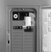
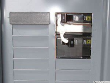
Possibly these two styles of interlock would work together.

1697379574032.png

1697379536426.png
 
Here is how my house is done.. how should I do my N/G bond?

Outside of house - Main panel N/G bond
Garage - Sub panel (connected to main panel)

There are ground, neutral and hots for split phase 120/240vac in the subpanel.

I want to take some of the sub panel circuits, or maybe the whole sub panel, depending on inverter size, and run them from an inverter.

I don't want the inverter to have it's own "earth ground", I want to use the existing building earth ground which will always be N/G bonded in the main panel.

Would the inverter need to make it's own N/G bond for its loads? If so, can it still use the ground wire going into the subpanel which connects to the main panel building ground, even though that is N/G bonded back at the main panel?
 
I have my generator inlet wired to the inverter and the inverter going to the panel with the interlock for the breaker.
Not sure if your inverter supports that configuration but it works for me.
 
If all grounds are continuous, and all neutrals are continuous, Neutral should bond to Ground at the first utility disconnect. Ground has a ground rod thereabouts as well.

My system has stacked 120V transformer type inverters, and those neutrals (and ground) tie into the house.

If someone has an autotransformer (or split-phase inverter with with center tapped transformer inside), then I think it is best for load neutrals to be continuous back to service entrance, but the transformer center tape should only connect to neutral when L1/L2 are disconnected from grid, so it doesn't fight to rebalance the grid.

I think inverter neutral connected to house neutral is fine for a system that is disconnected from the house 100% of the time. Any rule about N-G bond at "first disconnect" not withstanding. No different from a UPS with the breaker feeding it switched off. But you would have an issue if you ever interrupted neutral coming from grid service entrance.

Could be better to have an isolated "derived neutral", bonded to ground at the inverter's disconnect, for an inverter that never has grid on input.

I don't want grid L1/L2 to go through to loads, have a separate neutral, and have that neutral bonded to ground. In that case, all imbalance current would flow in ground.
 
That looks good. With the exception of AIO input and output can be connected together. Which would be a problem.
The problem is that you are trying to use the main panel as a feed and loads panel, for the AIO.
The easiest solution is to move the AC in breaker to the top of the panel. And make a custom interlock that keeps them from both being on at the same time.
I've done exactly that, with Sunny Island fed from a breaker in the main panel and also able to backfeed through interlocked breaker.
Can't remember if I ever let it power itself. Should be no great harm; it will detect and islanding situation, and if it doesn't then frequency and voltage will drift out of spec until it disconnects.
It could of course be either in phase or 180 degrees out of phase; out of phase mine would never sync and never connect, but keep trying.

All you have to do is manually turn off your 30A breaker feeding inverter before turning on 50A interlocked breaker coming from inverter.

Possibly these two styles of interlock would work together.

View attachment 172376

View attachment 172375
Thanks to you both for the feedback here. I think you're right that this is probably the best option, either an updated interlock which handles both or some sort of pivoting interlock like that second picture that also ties down into the next breaker down and forces it to be off if the interlock breaker is turned on. I've reached out to some interlock manufacturers to see if they see any options for my specific panel.

I'm wary of someone not realizing they could mess up the inverter if for example my wife is out of town so if an interlock isn't possible I'll likely just grab a battery charger or the chargeverter just to have that charge the battery directly then also plug the inverter battery in right on top of that, seems a bit more "not me" proof!
 
I want to use the existing building earth ground which will always be N/G bonded in the main panel.
This is correct.
Would the inverter need to make it's own N/G bond for its loads?
When it's the only source for the loads, yes.
Unless you are setup with a common neutral.
If so, can it still use the ground wire going into the subpanel which connects to the main panel building ground, even though that is N/G bonded back at the main panel?
Yes
 
Back
Top