diy solar

diy solar

My experiences finding the right black-start UPS for an off-grid solar system

fmeili1

Solar Enthusiast
Joined
Jan 19, 2022
Messages
333
Location
Arizona, Mohave County
I would like to share my experiences in finding the right black/dark start UPS for a solar system. It might be helpful for someone to avoid making the same mistakes as me.

First, you only need to take care about a dark-start situation if you have some sort of emergency shutdown relays or contactors or a PVRSS integrated in your solar system. These PVRSS, relays and contactors need an initial source of energy because they are designed as normally open (NO). So you need at least a bit of energy to startup your solar production. This comes usually from a tiny UPS which must not last very long, just long enough to activate the relays etc, to do the startup process until new solar/battery energy is available.

In my situation, I have relays between the batteries and AIO inverters, contactors between the grid and the AC-in's of my AIO's and a module based Tigo PVRSS. Everything is implemented just for an emergency situation to do a rapid shutdown of all external energy sources for the AIO's. I only need about a max. of 100W power from this UPS for usually less than a minute to drive the controller circuit with it's relays.

I've tested the following UPS's in the following order:
  • Using a very cheap "simulated" sine wave UPS (APC UPS BE425M - 425VA for about $65)
    • Because of the "simulated" sine wave, the relays and contactors getting hot and making annoying humming noises - NOT usable!
  • After that, I've tried a pure sine wave UPS with an acceptable price (CyberPower CP1000PFCLCD - 1000VA for about $170)
    • Because this UPS is not a "double conversion" aka "online" UPS type, it has a transfer time in case of a power outage. Even this transfer time is short (between 10ms-50ms), it's too much and my relays/contactors are dropping for a short moment which shutdown the solar system again - NOT usable!
  • After that, I've found only one small "double conversion" UPS (Eaton Tripp Lite SU700XLCD - 700VA for about $700)
    • It costs a fortune but I need a reliable online, pure-sine UPS for my situation. Unfortunately, the unit was not working reliable in case of a power outage (DC BUS unbalanced faults). So I've returned it - broken and too expensive!
  • After that, I've decided to build my own "mini - pure sine wave- double conversion - black-start - UPS". There are only 3 things required to do this. It has about 500VA power and the costs are about $280. The parts are the following:
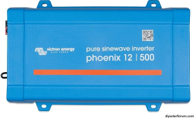
    1. Victron Phoenix 12V / 500VA, 120V inverter ($160)
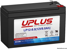
    2. A 8Ah AGM battery ($30)
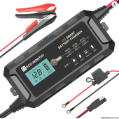
    3. A quality 10A 12V battery tickle charger ($90)
Putting everything in an air ventilated box and the budget mini UPS with pure sine wave, online with double conversion, is ready to go. Also it's very transparent if and how there may be a G-N-bonding and/or a common neutral situation. In existing UPS solutions it's sometimes a bit foggy how this is implemented and/or customizable.

These are the parts:

1699142331935.png1699142363741.png1699142414842.png
 
Last edited:
A short update after 3 days using it:
  • The Victron inverter stays nice cool and works flawless (a smaller version would have been more than enough, but it's ok). The fan is completely quiet.
  • The Victrons default is NOT G-N-bonded, but I want such a bond and the Victron could be reconfigured to establish a internal G-N-bonding (it's described in the manual; the case has to be opened and an internal ground wire has to be jumped from it's default clamp to a different clamp). To achieve the common-neutral setup which I want to have, the external GND clamp of the Victron has to be connected to system ground also.
  • At the first time I was not sure if the relatively small battery (8Ah) would be enough to use with this Victron because the manual requires about 40Ah battery capacity for this inverter. But because my power consumption is only about 50W (about 10% of what the Victron is able to deliver) I was giving it a try - it works without any issues!
  • With my relays, contactors and PVRSS it draws only 3-4Amps from the battery which would last for about 2 hours (usually it needs to run from battery only for a few seconds until I have power again from the solar system).
  • The charger has an AGM mode and it saves it's settings after disconnect from power (which happens in black-start situation). After power is back, the charger starting up in saved AGM mode again. So the charger could be permanently connected to the battery/inverter. The charger gets acceptable warm with it's permanent 3-4Amps usage (it gets warmer as the inverter).
  • Now I have to build a case with some vent openings for the three components to make the "online double conversion, pure sine, mini DIY UPS" nice looking.
 
Last edited:
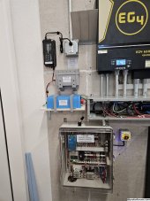
My side project to build a DIY blackstart mini UPS is now finally installed and is running without issues. Because of possible temperature problems, I've decided to not integrate all three components into one "UPS" enclosure, instead I've left them separate and 3D printed some brackets/cases to secure them on the wall. This is how it looks like.
20231112_074542.jpg
 
That box is beautiful. How do I get one like that and how do you attach things to the back of it? With screws?

Is it designed to take DIN rails only or as a universal backer board to accept any chassis mounted hardware?
 
My side project to build a DIY blackstart mini UPS is now finally installed and is running without issues. Because of possible temperature problems, I've decided to not integrate all three components into one "UPS" enclosure, instead I've left them separate and 3D printed some brackets/cases to secure them on the wall. This is how it looks like.
View attachment 177364
That looks like a DIN-rail mount for a Solar Assistant? I’ve been thinking about doing just that; did you model and 3D-print that yourself, or did you use something off-the-shelf?
 
That looks like a DIN-rail mount for a Solar Assistant? I’ve been thinking about doing just that; did you model and 3D-print that yourself, or did you use something off-the-shelf?
I've ordered it from Amazon for $10. I've installed a momentary button on top of the Raspberry Pi case to be able to securely shutdown the Pi for planned shutdowns (helps to protect the SD card). With this button, the Pi could also be restarted, in fact it toggles between restart and shutdown. To see the state of the Pi, I've also installed a LED to show if it's running or in shutdown status.

To add these two features, you have to mount the SA image (the one with the name "boot") with a PC and need to add two lines at the end of the existing file "/confix.txt".
  • Add the following line to control the button:
    dtoverlay=gpio-shutdown,gpio_pin=3
  • Add the next line to control the LED:
    dtoverlay=gpio-poweroff,gpiopin=23,active_low=0
Save the file and save the changed SA image and copy the image back to the SD card and install it on the Pi.

Connect the button on the Pi connector between GPIO3 (pin5) and GND (e.g. pin6).
Connect the LED with a 3.3kΩ resistor between GPIO8 (pin24) and +5V (e.g. pin4).
 
Last edited:
That box is beautiful. How do I get one like that and how do you attach things to the back of it? With screws?

Is it designed to take DIN rails only or as a universal backer board to accept any chassis mounted hardware?
Thanks!

I've found a nice box on Thingiverse and modified the size to be a bit larger as the battery itself to add some space for the two in wire car fuse holders. Also I've add some air vent holes because AGM batteries should not be enclosed completely.

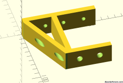
I've designed myself a bracket with OpenSCAD to hold the case on the wall. Here is a screenshot where you can see, how it's mounted on the wall. The wall is only a universal backer board and I mount everything with separate screws. The only DIN rail are used inside the controller circuit enclosure.

1699805409055.png
 
Thanks!

I've found a nice box on Thingiverse and modified the size to be a bit larger as the battery itself to add some space for the two in wire car fuse holders. Also I've add some air vent holes because AGM batteries should not be enclosed completely.

I've designed myself a bracket with OpenSCAD to hold the case on the wall. Here is a screenshot where you can see, how it's mounted on the wall. The wall is only a universal backer board and I mount everything with separate screws. The only DIN rail are used inside the controller circuit enclosure.

View attachment 177373
Oh sorry that one's great too. But I actually mean the product labeled QIL IPS. I could use a box like that and I love the clear door.
 
A short update after a couple of weeks using it:
  • I've noticed that the Victron inverter stops working always after 4 days of using it and showing an error "low battery voltage".
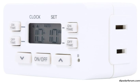
After a lot of investigation, it looks like that the used battery charger stops charging after some days. I was not able to find something in the manual about that but maybe it's inside their AGM charging algorithm to stop charging after some days (maybe an equalization algorithm thing?). So I've installed a small outlet timer which disconnects the charger for just 5 minutes every 24 hours.

It looks like, this solved my problem.

1701439196537.png

Maybe the intelligent battery chargers are not designed to permanently be connected to the battery to keep them charged while in parallel a permanent load is connected to the battery? I don't know.
 
Last edited:
First, you only need to take care about a dark-start situation if you have some sort of emergency shutdown relays or contactors or a PVRSS integrated in your solar system. These PVRSS, relays and contactors need an initial source of energy because they are designed as normally open (NO). So you need at least a bit of energy to startup your solar production. This comes usually from a tiny UPS which must not last very long, just long enough to activate the relays etc, to do the startup process until new solar/battery energy is available.

I thought RSDs guaranteed 0.6V or so per module of output power, so with a minimum string length as SunSpec and Tigo say you should do, you have probably 3V available at the MPPT input at all times. In what situations/configurations will this power not be available or not be used, to turn on the transmitter? Is it because you are using an external power supply that does not have a power path to some emergency bootstrap power converter on the MPPT?

I can imagine that something extremely power hungry like a CCA will have a tough time using the standby power
I'm not sure I understand your comments correctly.
The Tigo transmitter which communicates with all the Tigo TS4-A-2F switches (mounted under the PV panels) has a 120VAC to 12VDC power supply integrated to use it. The Tigo transmitter communicates via power line communication (via CT signal coupling) with the Tigo switches to turn them on. So the Tigo transmitter needs to be powered on to activate the solar modules (switching them ON).

Beside the Tigo PVRSS, I also use two relays to connect my battery racks with the inverters. These relays are NO (normaly open) and need a lot of power to close (600A relays need a huge current while the pick up coil is active). Also my DIY controller circuit which controls the emergency shutdown handling (one of the reasons why I've included these battery relays), needs power by itself and to drive all the relays and contactors.

If, for what reason ever, the emergency circuit would have been triggered and all relays/contactors are open, I need an energy source to close them to startup the system again.
OK, that makes sense.

What I'm getting at is, it's generally well known that there is standby voltage contributed by the RSD MLPE when RSDs are shut down. This is why there is a minimum and maximum string size that RSDs are allowed to have. The minimum string size, presumably is to guarantee a minimum amount of power. Maximum string size, to stay under the 30V limit.

So then the next question is. In what systems is this standby voltage usable for dark start? Is it zero? Or many? I have yet to find specs for how many mA is guaranteed from an RSD in shutdown state.

With Tigo, there is no connection from the PV conductors to the transmitter. So there must be some external box to grab the 5-29V of standby power from the shutdown string, and wake up the transmitter with it.

Are your battery rack shutdown relays DIY or part of a listing, manufacturer, or AHJ requirement in your ESS? Since you have a DIY system you need the power for that, unless you add something to try to harvest the standby RSD power. Sounds unpromising.
 
Are your battery rack shutdown relays DIY or part of a listing, manufacturer, or AHJ requirement in your ESS? Since you have a DIY system you need the power for that, unless you add something to try to harvest the standby RSD power. Sounds unpromising.
Yes, the emergency shutdown is completely DIY.

The state/county/city where I live does still not require module based PVRSS (it's still based on the old NEC 2008 standard). Because I've done the building permission paperwork process with the cities building department and the utility company by myself, it made things easier to get the permit after showing them my safety addons which are not required... they accepted my off-grid solution as a "generator" setup with a manual transfer switch where the generator is a "solar generator".

The system is installed inside the RV garage (behind the inverter wall is the master bedroom) and I will sleep with a better feeling if I know that the system will completely shutdown in case of an emergency. Because the AIO inverters does not have a build in rapid shutdown feature, I've decided to disconnect all possible energy sources for the AIO's in case of an emergency. These are
  • PV
  • battery
  • "AC-in" connected to the grid just as a backup in case batteries would be empty and no solar available (should not happen often)
To disconnect the PV, I've chosen the Tigo PVRSS system, to disconnect the batteries I'm using 600A/80VDC relays and to disconnect the "AC-in" from the grid, I'm using 110A 240VAC contactors.

An emergency situation could be triggered by
  • manual emergency push buttons (one inside and one outside of the house)
  • if one of the Kidde smoke detectors are triggered
  • remotely manually by intention via WiFi relay
  • automatic remotely (via integrated in my smart home system and camera detection), if smoke/fire is detected by the camera

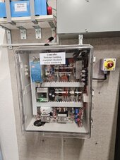
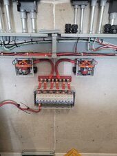
This is the DIY controller for emergency shutdown and monitoring.
20231220_070439.jpg

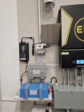
This is the DIY "online double conversion mini UPS" to drive the controller for up to 60 minutes (usually it's only required for a couple of minutes for a real blackstart situation).
20231220_070434.jpg

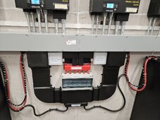
These are the two 600A battery relays which will be opened in case of an emergency (left picture while in building phase).
20230314_103011.jpg 20231220_070421.jpg

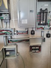
These are the two 110A AC-in contactors (in the right/bottom box) which will be opened in case of an emergency (left picture while in building phase right pictures shows the complete installation):
20230314_103029.jpg 20231220_070402.jpg
 
Wow that looks great!

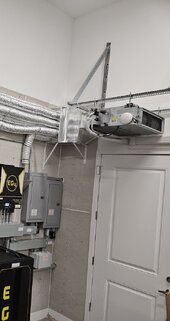
What’s the purpose of the flex duct? Is there some suction at the other end to try to pick up smoke?
Each AIO has three 6000 RPM fans inside that were NOT temperature controlled originally (see my posts here)! These beasts were unbelievably loud at the beginning and my wife showed me the "red flag" (our master bedroom is behind the wall...). Depending on load they were very loud or extreme loud - only two running speeds.

So I've modded all 18 fans with small temperature controlled PWM modules for putting between each fan and the mainboard. This worked, but after that, I've noticed that the noise was less but the AIO's still got warm enough and the fans speed up quickly again (but better than originally).

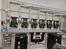
So the next step was to install a ducted mini split (high efficient, low BTU) to just inject cold air into the AIO vent inlets (which idiotically are at the top of the unit and not at the bottom - this produces a thermal shortcut because the hot air rises from the bottom was sucked in via the top vents... silly engineered...) and that is the reason for this 45 degree shields to separate a bit the cooled air from the exhausted hot air. The mini split is controlled via smart home rules depending on the AIO's temperatures.

Now everything is nice quiet, even under heavy load (y)
It's not only good for the relationship with my wife ;), I think it also will extend the lifespan of the AIO's

20231220_070412_small.jpg
 
Back
Top