diy solar

diy solar

Necessity of a Pre-Charge Resistor

DerBuchner

New Member
Joined
Oct 5, 2022
Messages
24
I have read various articles that one should not connect the components of a "solar system" directly, but that a pre-charge resistor must be used.

Sometimes I've seen that a connection is bridged by hand - temporarily - for a few seconds with a power resistor and only afterwards the actual cable is connected.
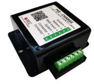
pre-charge-2.png

The explanation was, for example: When a device, like an inverter, is instantly connected to the battery, it is like a short circuit for the battery, which then supplies 100+ amps and kills the inverter. Because the capacitors suck themselves full and can't cope with it.
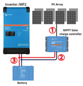
pre-charge.png

[edit] I forgot to mention: I intend to use a DIY LiFePO4 battery with 48 V and 14 kWh.

Question: Is such a pre-charge resistor really necessary or is this more like an urban myth?

(1) from the panels to the MPPT, I don't think so, a normal circuit breaker should suffice, right?

(2) at the connection MPPT <-> battery: do you need a pre-charge resistor here?

(3) at the connection battery <-> inverter: do you need a pre-charge resistor here?
 
Last edited:
Question: Is such a pre-charge resistor really necessary or is this more like an urban myth?

Depends.

(1) from the panels to the MPPT, I don't think so, a normal circuit breaker should suffice, right?

No pre-charge

(2) at the connection MPPT <-> battery: do you need a pre-charge resistor here?

No pre-charge

(3) at the connection battery <-> inverter: do you need a pre-charge resistor here?

Typically, yes.

Important with lead acid to prevent major spark/arc weld.

Important with Lithium to avoid having the BMS think there's a short circuit and cut the discharge circuit.
 
a pre-charge resistor must be used.
"must" is applicable only for devices with "high bus capacitance" from my gathering. Farad Capacitance threshold from "low" to "high enough to be worth precharge" is unknown to me yet.
Sometimes I've seen that a connection is bridged by hand - temporarily - for a few seconds with a power resistor and only afterwards the actual cable is connected.
yes, this manual capacitor pre-charge ritual is documented pretty well, serving as manual capacitance management. ohm's law etc.
(1) from the panels to the MPPT, I don't think so, a normal circuit breaker should suffice, right?
precharge, definitely not. only breaker and or fuse.
(2) at the connection MPPT <-> battery: do you need a pre-charge resistor here?
not needed. never heard of an mppt with such high bus capacitance on output to justify.
(3) at the connection battery <-> inverter: do you need a pre-charge resistor here?
depending on Inverter Wattage Rating, yes.
less than 1000 watts rating? likely no.
more than 2000 watts rating? yes territory.

in other threads regarding this issue, the topic arrived at Inverter DC Bus Capacitance as a primary deciding variable as to whether a pre-charge ritual is called for.

preference of operator for reducing stress on hardware is another major variable.

however, for 3000w and above inverters, i think precharge is desirable regardless.

automatic precharge vs manual precharge is a preference left to operator for convenience and how often expected need.

for now, i only try to implement pre-charge for inverters rated more than 1500 W. this is an amateur conclusion based on limited experience and reading anecdotes mainly on this forum regarding the sparking on connection phenomenon.

thank you for posting! very well formed question and demonstrates good theory understanding.
 
for the 300 W inverter, i use no precharge ritual or automated circuit.

for the 3000 W inverter, i shall delay the power up until automated pre charge circuit declares bus has been pre charged.

(300W is giandel inverter)
(3000W is victron multiplus)
 
to further clarity,
four classes of pre-charge method i see most:
  1. none
  2. manual
  3. timed
  4. sensing
most visitors here seem to use 1, 2 or 3.

type 4 is my preferred, and i don't see much.

if the precharge resistor is connected for the pre-set time and the bus does not reach an expected voltage threshold, this is an error condition that i wish for my system to Halt on
 
instantly connected to the battery, it is like a short circuit for the battery, which then supplies 100+ amps and kills the inverter. Because the capacitors suck themselves full and can't cope with it.
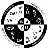
1) capacitance and voltage determine the X amps inrush according to Ohm's Law
2) sometimes it damages other components e.g. BMS while leaving inverter unharmed.

1665623575020.png
(my favorite version of ohm law)

((Battery Bank Volts)^2) / (Resistor Ohm) = Watts Precharge

approximately
 
I asked Sol-Ark this a while back about my 15K.

Their response:

Generally not required to pre-charge the caps, but that will depend on the battery in question. If using one of our battery partners, most options there are adeqaute to not require a pre-charge.
 
If I understand correctly, which is possibly not true, it is all defined by
  1. Device Capacitance
  2. Battery Voltage
  3. Battery Internal Resistance
  4. Circuit Ampere Rating
Combined with Ohm's Law.

Unfortunately not every parameter is available from the given manufacturer.
 
to further clarity,
four classes of pre-charge method i see most:
  1. none
  2. manual
  3. timed
  4. sensing
most visitors here seem to use 1, 2 or 3.

type 4 is my preferred, and i don't see much.

Up until now I was only aware of option 1 to 3.

I'd be very curious how 4 (sensing) works. Is there a ready made product that one can buy?
 
Up until now I was only aware of option 1 to 3.

I'd be very curious how 4 (sensing) works. Is there a ready made product that one can buy?
that variety is basically the timed one but it checks if the voltage on the bus got high enough before connecting. if the bus voltage is not high enough after X seconds of pre-charge then it would fail and not connect.

unaware of any premade stuff that does this
 
that variety is basically the timed one but it checks if the voltage on the bus got high enough before connecting. if the bus voltage is not high enough after X seconds of pre-charge then it would fail and not connect.

unaware of any premade stuff that does this
I understand. Did you build this by yourself or is there a product on the market?
 
I understand. Did you build this by yourself or is there a product on the market?
building it myself with components. the theory makes sense to me and i'm handy with microcontrollers and programming code and stuff.

if i get it working will be sure to post about it and share code and parts list.

basically an Arduino program that reads bus voltage on both sides repeatedly, and connects resistor for X seconds when Power Button is pressed. after X seconds, if inverter DC voltage is high enough, main contactor closes and resistor disconnects.

if inverter DC voltage is Not high enough, it disconnects resistor, aborts power up and would beep and or show a red light.
I'd be interested in your parts list, especially in your main contactor.

How do you control such high currents and voltages with an Arduino?
 
main contactor
gigavac contactor is my current choice.
sourced MX14CA and MX12TA by their model number system.
MX14CA : 400A, 24VDC coil
MX12TA : 225A, 24VDC coil
both have about ~2 watt continuous power use i think. there is a small surge on connect and then a small idle power. Strong Preference for Normally Open Type.
How do you control such high currents and voltages with an Arduino?
arduino controls a small relay or mosfet to drive the coil of a "contactor" (just a big relay?) and the contactor does the big ampere flow control. gigavac contactor is what i'm using for now.

the coil of the contactor i chose consumes relatively small DC amps so a small relay can control it.

Non-Latching Mini Relay

This is the relay I am using to control various devices such as contactor coil etc. It is Normally Open Non Latching type so will disconnect when power removed. I like that one because it has dedicated switching logic, so only power and signal needed.

hope this helps, cheers
 
I have never used a precharge resistor in my life. Didn't know it was a thing until i came to this forum.
me too. this forum was first place to see it

have had a spark for 350w,500w,2000w inverter (12V) and i just kinda tapped the lug haha. ⚡

next steps is 24V 3000VA (2400W continuous) inverter and i decided to research and implement an automated precharge circuit for power up sequence, to avoid strain on BMS from filling inverter DC bus capacitors too quickly.
 
some visitors mention manually connecting an incandescent lightbulb as a resistor to pre charge the inverter DC bus.

the bulb illuminating provides feedback on when current slows down. disconnect after light becomes dim sort of thing.

in this way "manual sensing" pre charge is also a method ??
 
Back
Top