diy solar

diy solar

Need some help with connecting to ground for my inverter!

coalfield

New Member
Joined
Sep 12, 2021
Messages
72
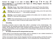
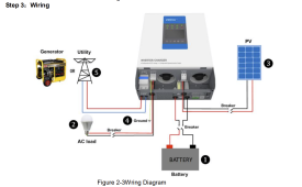
Really need some help... I am pretty worried about the safety of my system in its current state! I have an AIO inverter / charger from Epever (similar to Growatt), and am struggling to understand how to best connect the ground for the AC inputs and outputs of this system. Manual link

  • There is no ground input from the utility.
  • There is a ground on the AC Output.

The ground I have currently is from the ac input. However there is no 'input' for this and connecting it to the Ground connection on the output gives me a ground fault on the AC output when I test it.

My questions are:

  1. Should I be connecting the AC input ground anywhere?
  2. Am I meant to be connecting the Ground on the inverter to a separate and independent ground? (i.e. a rod)
  3. Should the ground also be connected to the panels, or should this be separate again?


The manual shows the following.

manual1.PNG
manual2.PNG
 
I am not familiar with the epever inverter, but every inverter I have ever studied or worked on ties the case ground, AC-input ground and AC-output ground together. I assume #4 in the above diagram where it shows a ground connection is in fact tieing case ground to earth ground. If that is the case, the AC is almost certainly tied to earth ground.

A more important question is "What about the Neutral-Ground bond"? This gets a lot more complicated and how the rest of the system is wired has implications on what the inverter needed to do (or not do) for bonding.

To know what to do for bonding, some of the questions that need to be answered are:
* What does the inverter do: A static N-G bond? A dynamic N-G bond? No N-G bond?
* Is the inverter Neutral-in tied directly to the Neutral-out?
* Does the inverter support tieing Neutral and ground on the output? (Sadly, some do not)
* Does the Generator have an N-G bond?
* is the AC input of the inverter tied into a breaker box? If so is there an N-G bond in the breaker box?
* Is the AC output of the inverter wired into a breaker box? If so, is there an N-G bond in the breaker box?

If the discussion of N-G bond is foreign to you, I suggest reviewing the series of resources on grounding. The first one is here and has links to the following 3.

 
@FilterGuy thanks for this I will have a look. It seems this subject is a lot more complex that I first thought!

For the questions you asked... is there any way I can identify the answers to these, for example using a mustimeter?

Agree with your point about #4 I suspect this is an earth ground and this is my priority to get this installed.
However question... if I were to connect the AC input to this earth ground, would this not create a ground loop on my house supply?
 
However question... if I were to connect the AC input to this earth ground, would this not create a ground loop on my house supply?
Yes, if the AC input Ground wire is tied to earth ground, you should NOT tie the case to ground.
 
For the questions you asked... is there any way I can identify the answers to these, for example using a mustimeter?
Some of the non-inverter things can be figured out quite easily. The inverter-related questions are a bit harder to figure out.

BTW: I am assuming you are in the US, Canada or Mexico..... if not, things may be very different for you.

* Does the Generator have an N-G bond?
When the generator is not running, put an ohmmeter between the neutral and ground output of the generator. If the resistance is near zero, it has an N-G bond. If the resistance is near infinite, there is no bond.

* is the AC input of the inverter tied into a breaker box? If so is there an N-G bond in the breaker box?
If your house is on the utility grid, your main breaker box will almost certainly have an NG bond (Assuming the house was wired to code in the first place).

* Is the AC output of the inverter wired into a breaker box? If so, is there an N-G bond in the breaker box?
Please describe what the output of the inverter is hooked to and if there is any place the neutral and ground are tied together.


I have to run right now. I'll post some questions later to try to figure out the inverter.
 
* What does the inverter do: A static N-G bond? A dynamic N-G bond? No N-G bond?
* Is the inverter Neutral-in tied directly to the Neutral-out?
* Does the inverter support tieing Neutral and ground on the output? (Sadly, some do not)
is there any way I can identify the answers to these, for example using a mustimeter?

I poked around and could not find any documentation on the EPEver inverters that would answer these questions. (It is almost criminal how some of the inverter manufacturers fail to describe this critical information)

Unfortunately, I don't know an easy way to figure out what the inverter does without actually hooking it up and doing some measurements.

Here are some tests to try to figure out what is happening with the set-up.

In all of the following tests, there should be no load at the inverter output.

1) With the inverter input connected to the grid and the grid driving the output, measure the AC voltage between neutral and ground at the inverter output.
2) With the inverter connected to the grid and the batteries driving the output, measure the AC voltage between neutral and ground at the inverter output
3) With the inverter NOT connected to the grid power and the batteries driving the output, measure the AC voltage between Neutral and ground at the inverter output

All 3 of the above tests are important.

If any of the above voltage measurements are more than a few hundred millivolts, there is no N-G bond in the circuit for that case.....and something needs to be done to remedy the problem. Unfortunately, even with the info these tests give us, we don't yet know enough to say how to safely remedy the problem. We will cross that bridge when/if we get to it.
 
wiring "rules" definitely vary by country. This is mostly about north american electrical house wiring to "some" code (do keep in mind that the electrical code has changed and so a 40yr old house is not wired the same as a 2yr old house).

filterguy has given you lots of good information, however, there are some caveats that are, well, "hidden" based on the manufacturer of equipment.

in the US your power comes in via a neutral and two "hot" legs...lets ignore phases for now and just focus on a normal 3-wire circuit.
Each circuit in your house is a "hot", "neutral", and ground (actually if your house is old enough you may not have a ground).
neutral and ground seem to be the same, they are NOT.
The neutral normally carries the current from the hot back to the power generator (it completes the loop) be it grid, inverter, or generator.
The ground carries current when something has gone "wrong".

your incoming power from the grid normally comes in with "hot" lines and "neutral" lines; somewhere near your powerpanel will be a grounding connection. Depending on year and electrician it will be a wire connected to a local rod driven in the ground, could be attached to rebar in your foundation, or metal plumbing pipes on your well...all depends on local rules and year things were done.
bottom line is that the grid give you "hot" wires and neutral wires..YOUR site provides a ground.

This is where bonding comes in..at ONLY a single spot in your structure do you want the grid neutral connected to YOUR ground.
In your house at a single point(usually your main power panel) is where this connection is made.
It caused "problems" if more than one bridge between neutral and ground exist...

here come the caveats that cause trouble...
generators may, OR may not, connect their ground to their outgoing AC neutral(provide bonding).
generators/inverters may, OR may not, actually document that your should attach generator ground to your structures ground.
Inverters may, OR may not, connect their ground to their outgoing AC neutral(provide bonding).

sometimes when you ask product support even they do not know or worse yet, actually give you the wrong answer.
Sadly you often need to get a meter and actually measure resistance between neutral and ground at the OUTPUT of your equipment.

I have an AIMS inverter that has a documented bonding jumper strap and when it switches to battery power IT bonds the outgoing neutral to the ground lug on the device.
I also have an MPPsolar LV2424, it does NOT bond neutral to ground lug when it switches over to battery (even though they said it does).

When you are measuring if there is a connection internal to the device, make sure you have completely disconnected from the grid.
You want to know if the device is actually providing a relay and bonding ground to output neutral when it is generating the power.

This is why you often see mention of a "transfer relay" so that you can:
1) make absolutely sure you never energize the grid and shock some poor guy working on the neighborhood power lines!!
2)make sure that when you switch to locally generated power you STILL have a valid single connection from your neutral to your ground
I cover most (all?) of this in the grounding resources I linked to in post #2
 
Yes, if the AC input Ground wire is tied to earth ground, you should NOT tie the case to ground.

The invertor has no AC input ground. It only has that shown on the diagram (#5).
Would the case not be grounded to the ground wire (#4 on the diagram) as a matter of course? There is no separate ground connection for the case?

BTW: I am assuming you are in the US, Canada or Mexico..... if not, things may be very different for you.
I am in the United Kingdom.. sorry should have said from the start! the plot thickens :ROFLMAO:
 
I am in the United Kingdom.. sorry should have said from the start! the plot thickens
Hmmm..... that puts the whole discussion outside of my comfort zone.... Grounding and bonding practices and standards are enough different in the UK that I am not very comfortable making recommendations.
 
What I read in the manual is the "ground" (#4) connects to the ac input ground (green) as well as the ac output green,, not white nor black!..
imo; It doesn't hurt to connect the metal case to the utility ground.
The ac output of the inverter must never connect to the grid.
Never use a new ground rod to connect ac. Only use the utility supplied green ground.
Never connect the white or black inverter ac output to any green or bare ground.
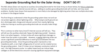
The only ground for the panels would be for lightning dissipation if needed.
 
What I read in the manual is the "ground" (#4) connects to the ac input ground (green) as well as the ac output green,, not white nor black!..
imo; It doesn't hurt to connect the metal case to the utility ground.

Thanks I tried connecting the AC input ground + the AC output ground to the inverter but the test plug I have is giving a ground error. Testing it on the AC input it works fine so its not liking that for whatever reason :(


Never use a new ground rod to connect ac. Only use the utility supplied green ground.

Is it OK to use a grounding rod for lightning dissipation just for the panels?
 
here come the caveats that cause trouble...
generators may, OR may not, connect their ground to their outgoing AC neutral(provide bonding).
generators/inverters may, OR may not, actually document that your should attach generator ground to your structures ground.
Inverters may, OR may not, connect their ground to their outgoing AC neutral(provide bonding).

The concept of bonding totally messes with my limited knowledge....

So I get this right... is the reason that the bond between ground and neutral does not just short the whole system, because the resistance of the ground is high compared with the circuit, but lower than going through your body for example (i.e. provides the protection).

In which case if the neutral is disconnected from the source, what's stopping the whole circuit shorting to ground? Sorry for what maybe a newbie question just trying to get my head around it, the thought of bonding the neutral to ground instinctively feels like a short circuit.
 
When the generator is not running, put an ohmmeter between the neutral and ground output of the generator. If the resistance is near zero, it has an N-G bond. If the resistance is near infinite, there is no bond.
The resistance is 5-10M Ohm so no bond, this is at the AC output of the inverter.


If your house is on the utility grid, your main breaker box will almost certainly have an NG bond (Assuming the house was wired to code in the first place).

Yes I am 99% sure this will be in place for the AC input


Please describe what the output of the inverter is hooked to and if there is any place the neutral and ground are tied together.

Wired directly into a plug socket. There is no bond in place there.
 
Yes I am 99% sure this will be in place for the AC input
Warning: I am not well versed on UK wiring, so take everything I say with healthy skepticism.

As I understand it, there are 3 separate schemes employed in UK residential power. You need to find out what your house uses.


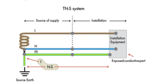
1) TN-S

1640032847369.png

With TN-S, the N-G bond is done at the Utility Transformer and the utility provides a solid PE wire to the residence. With this set-up, there is a very low impedance path from ground to neutral.

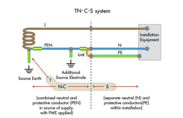
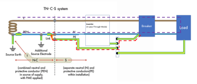
2) TN-C-S

1640033110644.png
With a TN-C-S system, there is a local Neutral-PE Bond. (I *think* the bond is part of the Uility wiring and is *not* done in the consumers wirring. With this set-up, there is a very low impedance path from ground to neutral. This set-up is similar to what is done in the US, but the bond is done in the consumers wiring.

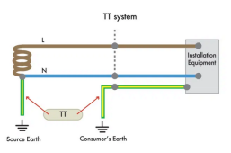
3) TT
1640033377863.png

In the TT system, there is no Neutral-PE bond. This means the impedance between the PE and Neutral is defined by the impedance of the earth ground. There is a high risk that a short from Hot to the PE would not cause a breaker to pop. Consequently, these systems should have a RCD breaker in order to make the system safe. (My understanding is that TT is only found in older homes. All newer construction has either TN-S or TN-C-S.


For the purposes of this discussion, TN-S and TN-C-S are electrically the same. They both have a very low impedance path between Neutral and P.E.
 
Wired directly into a plug socket. There is no bond in place there.

So, what we need to understand is what happens in various fault conditions at that socket or an appliance plugged into that socket. The conditions I am thinking of are these:

1) Short from Hot to Neutral:
2) Short from Hot to PE
3) Short from Hot to Earth Ground.

For now, let's ignore the inverter and look at what a typical house circuit would do in each of these cases.

1) Short from Hot to Neutral:
There would be a very high surge of current that would pop the breaker.

2) Short from Hot to PE
For TN-S and TN-C-S systems, there would be a very large surge of current that would pop the breaker.
For a TT system, the current would flow through the earth back to the utility transformer. Depending on the resistance of the earthing system, the current may or may not be large enough to pop a breaker. (This is where RCD breakers come into play. They will pop if a very small amount of current flows through the earth ground.)

3) Short from Hot to Earth Ground.
For all 3 types of systems, the current would flow through the earth back to the utility transformer. Depending on the resistance of the earthing system, the current may or may not be large enough to pop a breaker. This is where RCD breakers come into play. They will pop if a very small amount of current flows through the earth ground.


Now let's look at what happens when the inverter is in play. However, for this, we must look at each of the fault conditions for the following inverter states:

1) Inverter wired to the grid and the output of the inverter is powered by the grid.
In all of the inverter chargers that I have studied, the socket wired to the output of the inverter will act exactly the same as if it was just another plug in the house. I can not guarantee that is the case with your inverter.....but it probably is.

2) The inverter is wired to the Grid, but the inverter output is powered by the battery.
  • If there is a short between hot and Neutral, the breaker in the inverter will pop (I assume there is a breaker in the inverter) .
  • If there is a short between Hot and PE..... we don't know what will happen.
    * Many inverters disconnect the grid neutral from the output neutral but do not provide a low impedance path from neutral to ground. This leaves the circuit floating and if there is a short from Hot to PE, there will be no surge current to pop the breaker.
    * Some inverters disconnect the grid neutral from the output, but then automatically throw a relay that generates a low impedance path from Neutral to Ground. In this case there will be a surge of current and the breaker will pop.
    * Some inverters do not disconnect from the Grid Neutral from the output neutral. For TN-S and TN-C-S systems, there would be a very large surge of current that would pop the breaker. For a TT system, the current would flow through the earth back to the utility transformer. Depending on the resistance of the earthing system, the current may or may not be large enough to pop a breaker. (An RCD in the system would detect this and pop.) Note that if the inverter input is not hooked to the Grid.... then this type of inverter would always leave the output floating.
  • If there is a short between Hot and Earth ground..... we do not know what will happen, If the inverter output is floating.... nothing will happen because there is no path back to the power source. If the output is bonded either internally or through the grid, then-current would flow but may or may not pop a breaker. (An RCD would be needed to detect this case and open the circuit)

Many people on the forum feel that a floating output is ok because the only way to get a shock is through direct contact with hot and neutral. Since there is no path through the ground, just touching how will not shock you. I understand this position but I am uncomfortable with leaving the output floating. I would much prefer a system where the circuits can not float to some arbitrarily high voltage in relation to ground *and* if there is a short from hot to PE, the breakers immediately pop.
 
Warning: I am not well versed on UK wiring, so take everything I say with healthy skepticism.

As I understand it, there are 3 separate schemes employed in UK residential power. You need to find out what your house uses.

2) TN-C-S

View attachment 76523
With a TN-C-S system, there is a local Neutral-PE Bond. (I *think* the bond is part of the Uility wiring and is *not* done in the consumers wirring. With this set-up, there is a very low impedance path from ground to neutral. This set-up is similar to what is done in the US, but the bond is done in the consumers wiring.

I truly appreciate you investigating....

I am 99% sure my system is the TN-C-S System. There are 2 incoming conductors coming in, and then there is a 100A breaker from which point it splits out the Earth (see this video @ 25s in)

1) Inverter wired to the grid and the output of the inverter is powered by the grid.
In all of the inverter chargers that I have studied, the socket wired to the output of the inverter will act exactly the same as if it was just another plug in the house. I can not guarantee that is the case with your inverter.....but it probably is.
The inverter has 2 modes, a bypass mode (as per the above), and a Utility Charge -> Battery -> Load mode. Currently I don't use the bypass mode at all but in its name it implies it will directly pass the utility through.

2) The inverter is wired to the Grid, but the inverter output is powered by the battery.
  • If there is a short between hot and Neutral, the breaker in the inverter will pop (I assume there is a breaker in the inverter) .
There is no breaker in the inverter output, (there is one on the utility input) however I have added a breaker to the output as recommended in the manual.
 
Last edited:
I truly appreciate you investigating....

I am 99% sure my system is the TN-C-S System. There are 2 incoming conductors coming in, and then there is a 100A breaker from which point it splits out the Earth
OK.... Let's assume it is a TN-C-S system.

The inverter has 2 modes, a bypass mode (as per the above), and a Utility Charge -> Battery -> Load mode. Currently I don't use the bypass mode at all but in its name it implies it will directly pass the utility through.
OK.... Have you measured the voltage from Neutral to the ground wire? That will tell us if the system is floating.

There is no breaker in the inverter output, (there is one on the utility input) however I have added a breaker to the output as recommended in the manual.
Good.
 
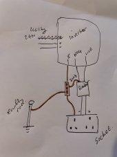
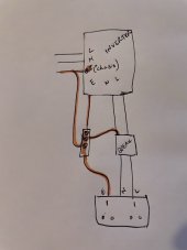
Is this what I should be doing? i.e. ignore the utility, but connect the Earth and Negative into the AC output breaker...

This way any grounding fault will draw a high current over the earth wire and trip the breaker?

Also connecting a earthing rod as an additional layer of protection (although not actually sure if that's needed?!?!)

IMG_3016.jpeg
(excuse the scrawl!)
Note: not sure what to do with the utility ground input.
 
Back
Top