diy solar

diy solar

New Lux Power LXP-LB-US 12k / GSL-H-12KLV-US with 200A AC Passthrough Current (US Market)

Status
Not open for further replies.
If I only AC couple (2) 5KW GT inverters and left the third inverter as a spare, I could connect the 6KW of solar panels to the new 12K hybrid inverter MPPT. GT inverters are designed for maximum production from available solar energy or off. The hybrid inverters may be better able to modulate and match the production from the solar panels with the consumption. I would think between the solar panels and the batteries that the AC couple inverters would normally be off during a power outage.
 
What particular model Fronius are you concerned about ?
I have a primo in use and a galvo as a spare. I don't have one of the IG in working state at the moment.
I didn't implement it, was just inquiring of the possibility. It was the Fronius ig3000. Can the Primo AC-coupled ?
 
In my case using Growatt 12Kw off grid to AC couple, my 2 EV chargers can soak up most of 15Kw grid tie inverters.
The total combined power if 12+15Kw.

But the problem arises when the cars being charged are full and the batteries are nearly full too.
The master AC couple inverter needs to tell the other inverters to lower their power or even to shut off.
In my test case using growatt inverter, I had to manually shut them off one by one to load balance.
slightly off topic: in your offgrid EV charging setup, are you throttling the EV charge demand ? or just let the Growatt+battery do the buffering ? I'm wondering how it works when there's insufficient juice from PV & battery. Thanks
 
slightly off topic: in your offgrid EV charging setup, are you throttling the EV charge demand ? or just let the Growatt+battery do the buffering ? I'm wondering how it works when there's insufficient juice from PV & battery. Thanks
No, I don't have a way to tell the charger to lower its power.
I only plan to use it as a way to bleed of excess power during mid day,
 
You avoid the question about having more power than 50A available when you are AC couple during a power outage..
I just didn't spell it out for you. What I said was you can couple any amount you want on the output side of the inverter. The inverter just provides the grid signal. You must specify how you are AC coupled when you talk about AC coupling. You can be AC-coupled on the input side of the inverter (grid-tied) and you can be AC-coupled on the output side of the inverter (also grid-tied when the grid is on). You can be AC-coupled on the output side when you are running off grid with an inverter only, or when the generator is also running. Its all AC. This means you can have 50A + 200A AC-coupled as long as you are consuming or discarding all of the energy you are producing. You can discard to the grid if you are grid-tied, or you can discard to your battery if you have batteries to charge, or you can discard to something else. You can have 50A + 2,000,000A as long as you can consume or discard the 2,000,050A.

The point here is that the AC-coupled energy is on the output side of the inverter and therefore has nothing to do with the inverter. The energy does not flow through the inverter. So the terminals won't melt, the relays won't fry, the batteries won't explode. The only thing that will happen if you don't consume or discard the excess energy is that the AC voltage will rise to unacceptable levels on the inverter outputs and your house, and once that happens the AC-coupled PV inverters will turn off completely. They are required by law to disconnect from the AC source immediately when the voltage level becomes abnormal. They will then wait for around 5 minutes before they will start sampling the voltage levels again and then turn on if all is right.

The only time you need frequency shifting is when the grid is off (intentional or not) and you don't have a way to discard all excess energy. Unless you are draining your batteries everyday and you have a gigantic battery bank, a power outage is more likely to occur when your batteries are already fully charged. This means that you won't have any place for excess energy to go when you are over producing. As has already been explained by others, this is a problem if the frequency shifting isn't immediate, or the grid-tie inverters don't respond quickly enough, or the feature simply doesn't work yet in the GSL inverter. We currently have no information about how fast the GSL inverter frequency shifting works. Nor do we have any information about how fast your PV inverters respond to frequency shifts. Nor do we have any information about what the GSL inverter does when abnormally high voltages appear on its outputs.

Assuming we never get any answers for any of those questions, a simple solution is to add a diversion load controller and load. This solution has already been mentioned at least twice. They are designed for this exact condition and respond essentially instantaneously to abnormal rises in voltage. That is their purpose and they are relatively inexpensive. So heat some water and if it gets too hot dump some water, or connect to an infinite load like a swimming pool if you have one, or try to boil the ocean or a stream if you are near one, or get a set of outside resistors, heaters, lights, or turbines, or just get a normally-closed SSR that turns off some of your inverters when they are producing too much energy.

A question that I don't believe has been asked yet is what does the GSL inverter do when it is running on generator power and PV power is AC-coupled to the output side of the inverter? Since their is a 100A relay for the generator does the excess power back feed the generator and burn it up? Does the GSL inverter detect energy other than from the generator and close the generator relay and switch to inverter power from the batteries to keep the PV inverters running? Does it leave the generator running or shut it down? Does the GSL inverter detect abnormal voltage and shut everything down? Does the GSL inverter somehow isolate the generator power from the AC-coupled solar inverters? If so how would they isolate generator energy from AC-coupled PV energy and still be AC-coupled? No matter what the answer is, you will still need a diversion load controller and a load if you want all of the parts to continue running.

Now you see why I didn't spell it out before.
 
Last edited:
The only thing that will happen if you don't consume or discard the excess energy is that the AC voltage will rise to unacceptable levels on the inverter outputs and your house, and once that happens the AC-coupled PV inverters will turn off completely. They are required by law to disconnect from the AC source immediately when the voltage level becomes abnormal. They will then wait for around 5 minutes before they will start sampling the voltage levels again and then turn on if all is right.
so technically the over voltage shut-off is a secondary guard while frequency shifting being the primary throttling ? would that be sufficient to avoid a dump-load requirement to prevent smoke (other than throwing away production) ? typically solar inverters are designed to keep cycling to check grid-AC integrity anyway, such as during outages, which can go for hours/days.

Also, is generator AC clean enough to AC-couple ? may be the newer inverter type generator. Has anyone successfully AC-coupled from generator power ? Thank you, it's like the more I learn the more I don't know
 
I'm just getting set up. Not quite to the point of AC coupling, but I'll let you know soon I hope.

Generator is a 6kW multiquip diesel. The power seems fine for the inverter. I can charge just fine from it as passthrough to the eps connections works well.

Strangeness - I got an error unexplained in the manual 'trip by Fac abnormal'. I had a similar weirdness with the mpp lv6548 not lock on. When I put a load on the generator separately (a 1500W heater) it slowed the generator enough to lock on properly and the fault cleared. It was able to charge well.

Two things I'm not yet successful at. The first is bms communication - eg4 lifepower4 is not able to connect as a lithium battery to the inverter as far as I can tell. I can use it by voltage rather than state of charge from the bms by setting it to lead acid mode. I may end up putting a raspberry pi in the middle with solar assistant to convert pylontech to eg4.

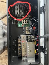
The other is silly. I can't figure out what I turn to tighten the PV input connectors! I need to turn something to tighten the circled connector. It looks like a tine square or Allen key but I can't find anything that fits.

(Finally, thanks to Hrschk for the password. As expected I waited until the weekend to start setting it up!)
 

Attachments

  • DEA769E5-98E8-4ED4-A5FD-4AED8F9130F4~2.jpeg
    DEA769E5-98E8-4ED4-A5FD-4AED8F9130F4~2.jpeg
    242.6 KB · Views: 22
I can't figure out what I turn to tighten the PV input connectors! I need to turn something to tighten the circled connector. It looks like a tine square or Allen key but I can't find anything that fits.
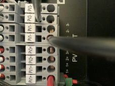
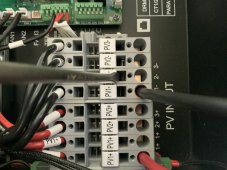
You put a small flat screw driver in the square hole and you pivot the screw driver with the handle towards the top of the inverter

That will open the metal part in the round opening, you insert the stripped wire there.
Then you release the screw driver and the cable is fastened by a spring.
There is no tightening, no special tool
 
Thank you! That makes perfect sense.
Just insert an appropriately sized flathead screwdriver as per the attached photos and give it a twist. It has a strong spring tension but that is good to ensure a strong clamp. It is also advisable to use wire ferrules.
 

Attachments

  • 231D79F6-5FA6-44E0-8D18-089D3C3066D7.jpeg
    231D79F6-5FA6-44E0-8D18-089D3C3066D7.jpeg
    212 KB · Views: 19
  • 567AEDC6-5B4D-47E2-99F3-F494FA12EBF5.jpeg
    567AEDC6-5B4D-47E2-99F3-F494FA12EBF5.jpeg
    261.6 KB · Views: 18
Thanks. I am getting a good connection now. I am not yet successful in getting any power in, but I think it is likely a settings problem. Still working on it.

For reference, though, I have two strings of 10 470 watt panels each. I'm seeing roughly 480 volts when I have the inputs disconnected. With pv1 and pv2 strings connected I see no voltage across anything.

I am off-grid, but running my generator in to the grid inputs (so that in future I can configure smart loads panel) and have "PV first" set in the charge menu. I have "feed-in grid" unchecked. On advanced, I have selected "pv1, pv2 independent" and "1:ct" set and the ct clamps are attached. I have selected RSD disable and removed the jumper.

I have no warning lights and no faults, but no PV generation.
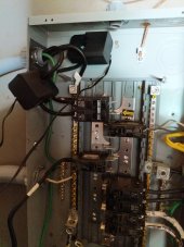
I found it easiest to set up my system with only the PV and batteries first and turn off all of the AC stuff in the beginning. So, you would turn off AC Charging and turn off forced discharge. Also, turn on Fast Zero Export. As to the CTs, mine have the arrows pointed the wrong way, so I had to face them TOWARD the AC source as opposed to facing them to the inverter for no net metering. So, you might check that to see if that is a problem. But, in your case, I'm assuming you have the CTs on the cables coming from the inverter, going into the AC ports.
I know this is a dumb question, but you did turn on the PV on the left side of the machine, right? the guy helping me actually didn't do this, so I just thought I would ask.
 
Oh no, please check the dumb assumptions! I suspect I've missed one of them. The switch on the side isn't it, though.

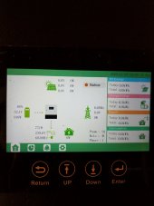
I've actually pointed the ct's to the generator, since that is acting as my grid, although the attached image makes me wonder if I have them right (generator is pushing in 800w but it shows 800w out to utility)

I was getting a "trip by Vac abnormal" when not running the generator, but batteries output through inverter ok without the generator running.

(Edit: no change in pv behavior with ct's on the output panel off the eps terminals)
 

Attachments

  • 16677649763837020197643634831322.jpg
    16677649763837020197643634831322.jpg
    123.6 KB · Views: 26
  • 16677652173053680921412837243230.jpg
    16677652173053680921412837243230.jpg
    98.9 KB · Views: 26
  • 16677658854994951274270442841037.jpg
    16677658854994951274270442841037.jpg
    143.8 KB · Views: 24
Last edited:
For reference, though, I have two strings of 10 470 watt panels each. I'm seeing roughly 480 volts when I have the inputs disconnected. With pv1 and pv2 strings connected I see no voltage across anything.
With your PV strings connected you should see 480 volts at where you insert the screwdriver to open the clamps.
If you do see voltage there but none on the display, the only other thing could be the switch on the left of the inverter.
That is a DC disconnect switch.
Make sure that one is in the ON position and you should see an input voltage at the color LCD
 
Oh no, please check the dumb assumptions! I suspect I've missed one of them. The switch on the side isn't it, though.

I've actually pointed the ct's to the generator, since that is acting as my grid, although the attached image makes me wonder if I have them right (generator is pushing in 800w but it shows 800w out to utility)

I was getting a "trip by Vac abnormal" when not running the generator, but batteries output through inverter ok without the generator running.
Yeah, makes me wonder if it's a problem with the arrow sticky on the CTs or if it's a problem with the inverter. I ran my central heat and air the other day with my batteries and PV turned off and it told me it was exporting power (like 24kw!!). But, I couldn't possibly have been because there was no power to export and the power meter showed me buying power, not exporting it. I need to check to see if I've gotten a firmware update because after I had this problem in the beginning, GSL had me face the CTs the other direction (the wrong direction). And, the problem was fixed. but, now it's back again, so maybe they've updated the firmware on my box.

The CTs need to be pointed to the thing that is receiving the power. So, whether it be the grid or the generator, it should be pointed toward the inverter because that is the direction you are sending the power.
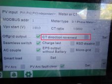
There is also a software setting to reverse the CT direction
IMG_20221106_123914783.jpg
 
With your PV strings connected you should see 480 volts at where you insert the screwdriver to open the clamps.
If you do see voltage there but none on the display, the only other thing could be the switch on the left of the inverter.
That is a DC disconnect switch.
Make sure that one is in the ON position and you should see an input voltage at the color LCD

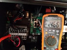
I do not see the voltage there. I see the voltage when the wires are not connected to the terminals, but when connected there is about 1.5V.
 

Attachments

  • 16677660809264733198108495739531.jpg
    16677660809264733198108495739531.jpg
    233.5 KB · Views: 13
I do not see the voltage there. I see the voltage when the wires are not connected to the terminals, but when connected there is about 1.5V.
Triple check to make sure the spring contacts are not sitting on the insulation of the wire. Do you get voltage at the end of the PV wires? (Obligatory - be careful in testing this, as this level of DC voltage can kill!)

BTW, you can ignore the CT's at this stage, as they do not affect PV voltage or generation as seen by the inverter at all. The inverter will run fine without CT's attached, it will just show all energy produced as going to load.
 
I do not see the voltage there. I see the voltage when the wires are not connected to the terminals, but when connected there is about 1.5V.
You forget to mention it is NEGATIVE 1.5 volt. Something is serious wrong
You are 100% sure the wires are stripped long enough, if the metal clips on the insulation it will make no contact.
should be at least 1/2-3/4 " stripped.
What I am about to suggest is possibly lethal, so don't do this if you don't feel comfortable doing so.
taking one of the wires out of the connector, leave the other one it.
put one of your multi meter pins on the one wire that stays in the connector, with the other one touching the stripped naked copper wire.
If you measure 400+ volts, but not when connected in the inverter, you have a high resistance in your chain of panels somewhere.
Also please note the polarity
If it shows -400+ volts you somewhere made a wrong connection.
I believe this unit has a reverse polarity protection but that would explain why you see -1.5 volt when connected!
 
Ok! I can now confirm that I am an idiot, and that this machine has advanced anti-idiot reverse polarity protection!

Thank you. I had reversed my wires as they came into the external PV fuse box and not noticed the negative voltage indicator.

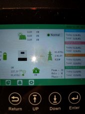
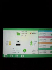
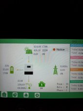
(Just editing to add the lovely picture of charge and invert happening :)
 

Attachments

  • 16677726470864560950249228003196.jpg
    16677726470864560950249228003196.jpg
    91.8 KB · Views: 27
  • 16677729883983127730305197254845.jpg
    16677729883983127730305197254845.jpg
    90.3 KB · Views: 27
Any news on the new firmware?
Hope they fix most of the problems found in the current release.
 
Is GSL still the recommended vendor to purchase from?
My vote is no that GSL is not the recommended vendor.

However, I'm waiting on delivery for two from GSL with extremely low expectations. Admittedly, I have no hands on experience with these inverters. I only have buyer remorse from all the reported issues and problems. So far, GSL support has been limited to saying that a new firmware update will be release within a week.

Yes, and there has been many firmware releases. As fromport pointed out, they are without any firmware release notes, so no idea what was supposedly fixed, if anything. After weeks of firmware updates, to my knowledge, these inverters are still not performing all functions per their advertised specifications. I don't even know, what reported issues or problems were actually fixed.

However, the opinions that really count are the people that have actually installed these units.
 
Last edited:
Status
Not open for further replies.

diy solar

diy solar
Back
Top