Hi
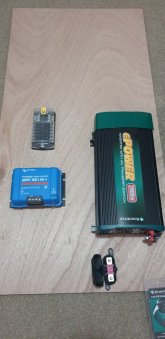
I am new to solar and DIY builds, I live in Australia so plenty of sun, I am very interested in building the 400watt system on will's video, or something bigger if possible, not an expert on amps and watts, would like some advice on breakers between, dc fuse box and the inverter also between the inverter and the mppt controller, I have purchased this invert and controller below.

 www.mygenerator.com.au
and
www.mygenerator.com.au
and
 www.mygenerator.com.au
so my question is what amp circuit breaker would I need between these two devices, also would 4 gauge wire be ok to use with this setup and 6 gauge from the controller?
Thanks in advance, for any advice
Mike
I am new to solar and DIY builds, I live in Australia so plenty of sun, I am very interested in building the 400watt system on will's video, or something bigger if possible, not an expert on amps and watts, would like some advice on breakers between, dc fuse box and the inverter also between the inverter and the mppt controller, I have purchased this invert and controller below.
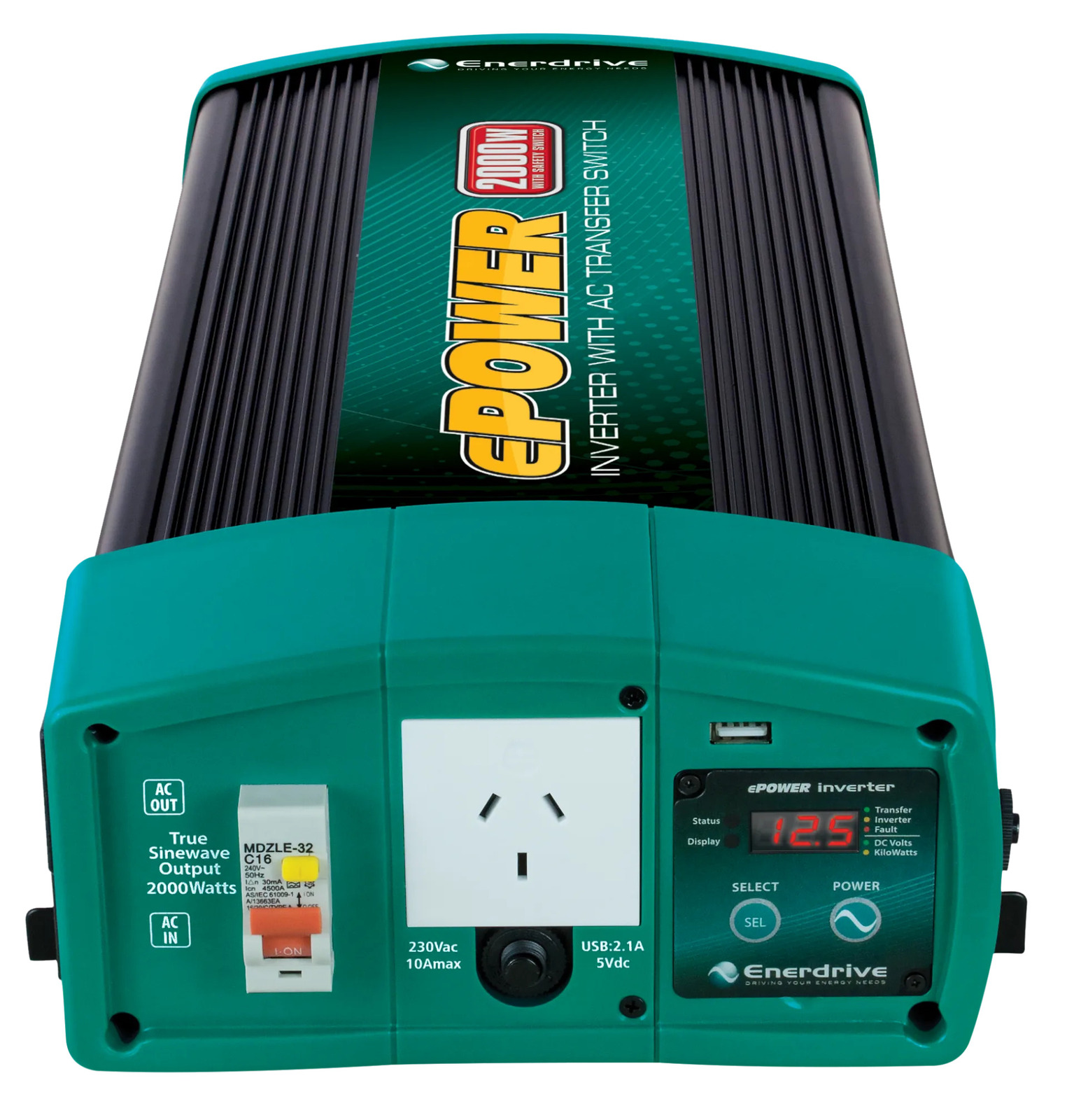
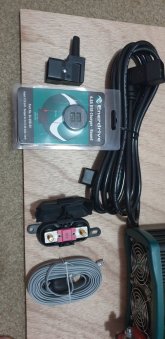
Enerdrive ePOWER 2000W Pure Sine Wave Inverter | Caravan & RV | Power Inverters & Adaptors
Shop Enerdrive ePOWER 2000W pure sine wave inverter from My Generator. We provide a comprehensive range of high quality power inverters, battery chargers and generators to suit every budget!
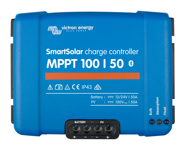
Victron SmartSolar MPPT 100/50 Charge Controller
Victron SmartSolar MPPT 100/50 Charge Controller - Victron - Victron SmartSolar MPPT 100 VOC / 50A Charge Controller, 5 Year Warranty
www.mygenerator.com.au
so my question is what amp circuit breaker would I need between these two devices, also would 4 gauge wire be ok to use with this setup and 6 gauge from the controller?
Thanks in advance, for any advice
Mike