diy solar

diy solar

No more Inverter needed in future ?

Thanks for sharing that. Looks interesting but appears cost is pretty high comparatively and from my understanding it is its own inverter by use of its own internal transistors. I could be wrong but it does use an inverter, just itself as one.
 
Yeah .... kinda sounds like the BMS is also an inverter. Possible different technology to achieve it.
 
just found this interesting and wanted to share .
Interesting, but unfortunately, seems to be single-phase (so not going to be suited for US split-phase power).

Still, I’ll be interested to see the manual once it’s available. Since is says it can be charged in DC, that suggests it has an integrated Solar Charge Controller and since it sounds as though it can be used to power loads, it must either communicate with an external power meter or include a CT sensor or two.

At that point, it would basically be a true Battery + Hybrid All In One…

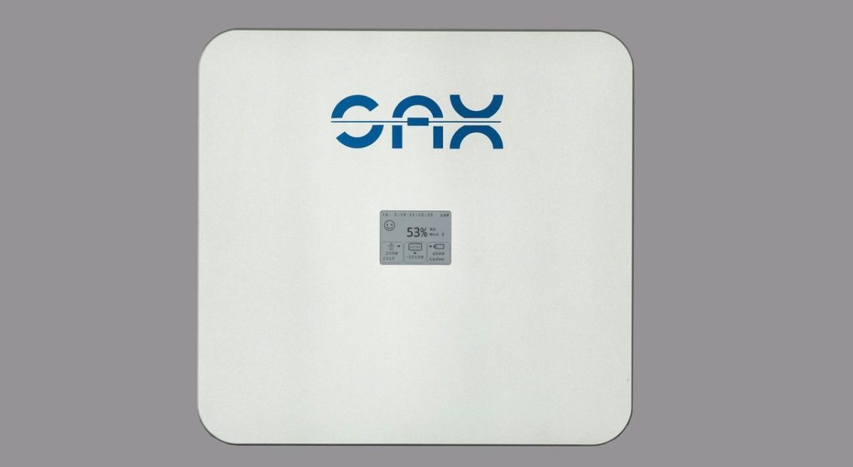
Here is their website: https://sax-power.net/produkte/sax-power-home/

Confirmed that is used an RS485 or Wireless Power Meter.

For a 4kW Hybrid Invrerter with integrated 5.1kW LiFePO4 battery, the price is actually not too bad…

As a ‘plug in’ it almost sounds as though you can plug it in through a dedicated outlet on a dedicated circuit and it’ll just charge when there is excess AC energy to spare and self-power when loads would otherwise begin consuming grid energy.

I’ve been waiting for a product like this - I think it’s the Wave of the Future…
 
Last edited:
Also, I’ve understood from their website that their product is a pure AC-coupled battery with no option to charge in DC.

The claim of 99% efficiency from BMS-based inverter replacement / emulation is fantastic, but the parent company has a long history in power electronics and they have landed Walden International as a major investor, so I think this is a technology to take seriously.

An AC-coupled battery that communicates with a CT-sensor-based Energy Meter is exactly the product I’ve been awaiting, so this is an exciting development (whether they can actually deliver a true 99% or 98% round-trip efficiency or whether the reality is only 80-90%…).
 
Sounds nice, and I do think it will have a better efficiency due to the lack of transformers.

However, it still does require mosfets or similar, unlike that link says. It's simply not possible to switch high-current DC using a H-bridge to AC otherwise, especially if you want to archive some sine-wave-like.

For a square wave, you could use theoreticly use relays, thus making it truely fet/transistorless switching, but that's noway near anything reasonable (apart from relays not liking high current 50Hz switching)
They apparently have a patent.

We should see if they’ve filed anything in the US yet…
 
Sounds nice, and I do think it will have a better efficiency due to the lack of transformers.

However, it still does require mosfets or similar, unlike that link says. It's simply not possible to switch high-current DC using a H-bridge to AC otherwise, especially if you want to archive some sine-wave-like.

For a square wave, you could use theoreticly use relays, thus making it truely fet/transistorless switching, but that's noway near anything reasonable (apart from relays not liking high current 50Hz switching)
Yes. The DOE has been throwing some money around in the way if SBIR grants in order to promote this technology. My buddy was able to glom onto some of those DOE bucks and a few landed on me. It's interesting, but a little on the complex side. I'm surprised to see something in production already. The Germans do a nice job :) I love my Volkswagen.
 
If you look here, you can see he title of their patent which was filed on November 7th, 2019: https://www.northdata.com/SAX+Power+GmbH,+Erbach/Amtsgericht+Ulm+HRB+737733 (I’m not able to access it without Premium Subscription and can’t translate German).

Also found this: https://topicplay.com/v/8920

And this: https://www.ees-europe.com/news/exp...-systems-alternating-current-without-inverter

And here is a datasheet: https://sax-power.net/wp-content/uploads/2020/05/sax_power_data_sheet-1.pdf
 
Sounds nice, and I do think it will have a better efficiency due to the lack of transformers

.

However, it still does require mosfets or similar, unlike that link says. It's simply not possible to switch high-current DC using a H-bridge to AC otherwise, especially if you want to archive some sine-wave-like.

For a square wave, you could use theoreticly use relays, thus making it truely fet/transistorless switching, but that's noway near anything reasonable (apart from relays not liking high current 50Hz switching)
I don’t understand how conventional high-frequency inverters are designed, but from that interview I linked to, it sounds as though SAX is using a high-speed switching network ala BMS to generate a sine wave by switching cells in and out of the series string.

I have no idea whether that would be more efficient or not, but BMS transistors switching ground certainly don’t consume 5-10% of the power passing through them…

What I don’t understand is how they are generating ‘negative’ output voltage (versus ground or ground-tied neutral) but if you you picture taking a 230VAC wage form at 50Hz and mapping it to a low of 0 volts and a high of 230 volts, they seem to be changing the battery string length at high speed to generate a ‘staircase’ approximation of that waveform and its inverse.

Again, no idea how they are going negative but if you powered a resistive load in that way it would generate the same power you’d get from a true 230VAC waveform.

And again, no idea whether it delivers improved efficiency (though the relative of BMS ground-switching transistors gives me hope ;)).

Oh, and if I’m right about this, switching is way higher than 50Hz. Even 500Hz wouldn’t be enough. Switching speed for the staircase emulation would probably need to be in the kHz range (~1mS between steps).
 
You can get a negative powersupply by changing the center tab. This doesnt have to be the negative of the first battery.
A battery and inverter are ‘floating’, there is no reference to ground.
If you serieconnect 2x12v to make a 24v battery, your just using the - from the first and the + from the second battery, and connect the other 2 together to create a serie string.

However if you’re using the wire beween those 2 cells to create a third point, acting as 0v, the first battery will provide +12v, while the second battery will provide -12v
So it will work as a dual feed powersupply

If you serie connect many 3.2v cells to get 220v (36x3.2v in series) and use the connection between cell 15 and 16 as your reference (0v) you end up with + and - 115v
Than its just a matter of switching between both with 60hz and you have a 115v square wave feed, which works with a resistive load.
Adding a cell switcher would create a modified sine wave with steps of 3.2v. Add some capacitors and filters to smooth the these steps and you basicly have an inverter.
However it does require some decent cell mangement since your discharging the individual cells at different rates and periods.

Note: calculations are not fully correct, the peak of a sine wave is sqrt2 higher than the rms rated voltage but you’ll get the idea

A typical inverter is either low frequency or high frequency.
A low frequency inverter uses mosfets to create a sine wave with 50/60hz which is fed into a transformer to boost to the required output, just like a regular substation or grid works.
Disadvantages is it requires heavy transformers (=expensive), benefits it can handle surges better and is solid

High frequency inverters use much higher frequencies, typical 100khz or so. This causes the transformer to be much more effective, so they can be much smaller. Cheaper and less weight. Disadvantages they can’t handle surges as good as low frequency ones.

For regular use, high frequency ones are more common due to their price/performance

However, both uses transformers which will cause losses, depending on the load 80-90% efficiency is common. Bypassing this with direct high voltage to sine wave will allow you to get 95+ effficiency I guess.

These high voltage systems are nice to use as addition to the grid (act as a powerwall), charging with solar inverters (if they are able to see the generated solar someway) or eg charging at periods with low kwh prices (some grid companies offer prices based on the availability - cheap offpeak or with plenty of solar/wind unused, expensive with less available power)

For offgrid i would prefer 48v or so since thats much easier to handle, safer and allows easy available chargers for solar and so on
 
Last edited:
I believe they are switching the battery connections around. If you need to get to the top of the sinewave you put all the batteries in series. I could be totally off target tho.
 
You can get a negative powersupply by changing the center tab. This doesnt have to be the negative of the first battery.
A battery and inverter are ‘floating’, there is no reference to ground.
If you serieconnect 2x12v to make a 24v battery, your just using the - from the first and the + from the second battery, and connect the other 2 together to create a serie string.
Yes, I see. So you would also be able to get split-phase output ‘for free’ (each 120V output leg is being independently generated). I suspect this is what SAX power is doing.
However if you’re using the wire beween those 2 cells to create a third point, acting as 0v, the first battery will provide +12v, while the second battery will provide -12v
So it will work as a dual feed powersupply

If you serie connect many 3.2v cells to get 220v (36x3.2v in series) and use the connection between cell 15 and 16 as your reference (0v) you end up with + and - 115v

Than its just a matter of switching between both with 60hz and you have a 115v square wave feed, which works with a resistive load.
Adding a cell switcher would create a modified sine wave with steps of 3.2v. Add some capacitors and filters to smooth the these steps and you basicly have an inverter.
I suspect this is exactly what they are doing.
However it does require some decent cell mangement since you are discharging the individual cells at different rates and periods.

They make a big deal about exactly that. They monitor all cell SOCs and make decisions about which specific cells to switch into and switch out of individual ‘steps’ based on their (relative) SOC (so it is supposed to be dynamically self-balancing).

Note: calculations are not fully correct, the peak of a sine wave is sqrt2 higher than the rms rated voltage but you’ll get the idea
Yes, I figured that was a detail not getting sidetracked by…

A typical inverter is either low frequency or high frequency.
A low frequency inverter uses mosfets to create a sine wave with 50/60hz which is fed into a transformer to boost to the required output, just like a regular substation or grid works.
Disadvantages is it requires heavy transformers (=expensive), benefits it can handle surges better and is solid
Yes, understand.
High frequency inverters use much higher frequencies, typical 100khz or so. This causes the transformer to be much more effective, so they can be much smaller. Cheaper and less weight. Disadvantages they can’t handle surges as good as low frequency ones.
Yes, I own a high-frequency PSW…

For regular use, high frequency ones are more common due to their price/performance

However, both uses transformers which will cause losses, depending on the load 80-90% efficiency is common. Bypassing this with direct high voltage to sine wave will allow you to get 95+ effficiency I guess.
So so suspect this is exactly what they are doing (and it probably also means absolutely no peak capacity beyond the rated capacity (unless there are heat issues causing them to limit the length of time at various output levels).

These high voltage systems are nice to use as addition to the grid (act as a powerwall), charging with solar inverters (if they are able to see the generated solar someway) or eg charging at periods with low kwh prices (some grid companies offer prices based on the availability - cheap offpeak or with plenty of solar/wind unused, expensive with less available power)
Yes, as a grid-assist hybrid battery, this looks pretty attractive. I wonder if the same ‘staircase’ technology can be used to charge cells as well as discharge?
For offgrid i would prefer 48v or so since thats much easier to handle, safer and allows easy available chargers for solar and so on
As long as you have some AC-coupled power available when the grid goes down, I think this could be attractive for backup power as well, but the issue then becomes where does the grid-simulating sine wave come from in order to activate the AC-coupled inverter(s)?

I suppose if the filtering is gone well enough, this technology could start pushing out power to activate the AC-coupled solar inverters at which point it could begin charging the battery to maintain the simulated grid signal by matching charging power to solar power - load power…

Whether it can throttle-back power try though frequency-shift or voltage shift might be another question, but the basic concept of initiating power ‘push’ before transitioning to power ‘pull’ when there is AC-solar power available seems like it should be possible…

I’m starting to get excited about this. It more truly is an AC-battery compared to slapping a battery charger and an inverter on a DC battery ;).
 
Last edited:
Back
Top