diy solar

diy solar

Problems with adding more panels

pulper11

New Member
Joined
Feb 14, 2022
Messages
120
Hello - I'm trying to figure out what my next move is to upgrade my solar within (hopefully) the constraints that I already have.

Background:
Right now I have six 310W panels on my garage roof facing South. 3S2P. That's the most I can get on the garage in this direction on the roof. The weather adjusted VOC is slightly over 50V each. The DC is brought into the house with 10 gauge wire through a trench. In the house, it goes through a disconnect box, then to the Morningstar Ground Fault Detection Device (600V model). This goes to the MPP LV6548. I have two Trophy Batteries that are charged through the LV6548. Trophy Battery 48V110C-1. I have a critical loads subpanel that right now for testing has only one circuit. My main panel is connected to the LV6548 through a 60A breaker. The plan eventually after testing is to use Solar first, then battery, then the main electric power. Right now, I haven't added the main electric power.

What I want:
I have six more panels available to put up. Two of those for sure will be on the South facing wall of the garage, attached directly to the wall using superstrut. I am hoping I can figure out how to connect these two panels to the panels already on the garage roof without having to go through the roof again. After this, my array will be 4S2P. I would like to put the four additional panels on the other side of the roof (facing North). However, I am limited here b/c of the following:

Potential Problems:
1. I cannot connect 5 panels in series as the LV6548 is 250V per MPPT and if I connected 5 in series, I would be above this. Also, as these additional panels are facing away from the sun, I wouldn't want them connected in series to the panels facing the sun.
2. B/C of the weird requirements for grounding the PV circuit with the LV6548, I had to purchase the Ground Fault Protection Device (GFPD). If I wanted to use the second MPPT on the LV6548, I would have to buy another GFPD. I believe they are about $450, so I'd prefer not having to do this.
3. I could use a microinverter for each of the additional panels. However, that's not cheap either and I have no idea how I would route the AC power from these inverters into my current system to use for circuits and for charging my batteries.
4. I could scratch the LV6548 and go with something that has a 500V input. The EG4 3kW inverter would be a possibility.

Questions:
Is there an option I haven't considered? Are my issues above correct?

Thank you!
1. Good catch on not exceeding the voltage, and you're correct about not connect opposite facing panels in series. The 250v limit on the LV6548 is probably my only complaint.
2. I'm not following the part about weird requirements for grounding the PV circuit. I don't know of anyone else using these inverters who is doing what you're talking about. I have an Aims disconnect outside for each pair of strings I have, then I have DC breakers on each string inside the garage where my system lives. The only thing that should be grounded on the panels are the frames. Mine are grounded back to the ground on the main panel where the N-G bond is located.
3. I'm no expert on microinverters but I don't think that's what you would want to do for this application. Maybe someone else can chime in on this.
4. You could go with the EG4 3kw but you're giving up a lot if you do. It has roughly half the production capability. Also, going along that line of thinking wouldn't you still have to punch another hole in your roof? In any case, I think you would be taking a step backwards with the 3kw. Don't get me wrong - I like the 3kw and will be ordering one soon for a mobile cart.

Another alternative to punching a hole in the roof would be to go over the eave and back underneath then go through the soffit or wall. Probably need to do so in conduit and it also depends on code where you are located.
 
Thanks so much for your response! I appreciate it.
Regarding the roof, now that I've done it it isn't terrible. However, I'm hoping that somehow I can bring the solar wires for the two additional panels through the previous hole that is covered with this:


Or of course bring the wire down to the panels through the same hole.
I think I just have to wrap my head around the logistics here.

Regarding the grounding, I've been part of a few discussions about it. If you start on this post and continue for a page or so, you'll probably get the gist of what I'm referring to.


I think what you're indicating about the microinverters is probably true. But that was perhaps one option to explore.

Regarding the EG4, could I purchase one and use it side by side with the LV6548? The new panels would use this inverter. Specifically, I'm not sure if I can charge the batteries with both the LV6548 and the EG4 at the same time and use the critical loads subpanel connected to both (perhaps making it 240V)?

Thanks again!
Good deal on figuring out the roof wiring.

On the grounding, they're talking about removing the grounding screw in the unit. This was something we had to do on pre-2023 units (or thereabouts) when we stacked two of the units. Beyond that they're also discussing grounding the frames of the panels. You'll need to do this no matter which inverter you use, and it should be grounded back to your existing ground for the house, as should your subpanel and inverter (but only one N-G bond). Grounding has fueled a ton of threads on here and there's still some back and forth on the best or proper method, but there's really nothing weird or different on the LV6548. The general consensus is to use a single ground. I know some may disagree but that's how I did mine.

Can you run the EG4 side by side with the LV6548? Well, yes, but you'll need to feed a separate panel or at least separate 120v circuits. A separate panel would be best. Just because you can do it doesn't mean you should. :)

If you feed one panel with Inverter A feeding L1 and Inverter B feeding L2 it would work but if someone plugs in a 240v breaker and tries to power a 240v load you're going to blow stuff up. That's true even if it were two of the LV6548 unless you configure them for split phase. So regarding your question about making it 240v with two different inverters, no it would NOT work. If you're going for 240v now or some time in the future you definitely need to make sure you understand how that works and design and build accordingly. If you want 240v then you need to match the LV6548 and configure the two inverters to run split phase. It's very common and I've seen very little problems on here. I've had zero problems with mine in that configuration.

Yes, you should be able to charge the battery from two inverters, no matter how you do it.
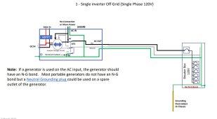
Thanks again for your help here. I was under the assumption that @FilterGuy had decided that the hall effect sensor was still needed, hence the morningstar GFPD. However, it appears at least to me that this is no longer the case since I found a document from him that indicates there is no need for this. Here is a screenshot of his diagram for a single LV6548:

lv6548 grounding page.jpg
So, it would appear to me that if the negatives on my battery are grounded, then there is no need for the GFPD. I'd still keep it for the six panels already setup, but now I can put three on the garage wall facing the sun and use the other MPPT. I wouldn't worry at this time about using the other facing side of the roof. I put an extra piece of 3/4" conduit in the trench that I hopefully can use for the additional circuit.

If this is all correct, do you have any suggestions on how to ground the negatives of my battery? Just place a terminal on two ground wires, attach them to each negative lug, and then to the service or critical loads panel grounding bar?

Thanks again for your help. Much appreciated!
 
Thanks again for your help here. I was under the assumption that @FilterGuy had decided that the hall effect sensor was still needed, hence the morningstar GFPD. However, it appears at least to me that this is no longer the case since I found a document from him that indicates there is no need for this. Here is a screenshot of his diagram for a single LV6548:

View attachment 158422
So, it would appear to me that if the negatives on my battery are grounded, then there is no need for the GFPD. I'd still keep it for the six panels already setup, but now I can put three on the garage wall facing the sun and use the other MPPT. I wouldn't worry at this time about using the other facing side of the roof. I put an extra piece of 3/4" conduit in the trench that I hopefully can use for the additional circuit.

If this is all correct, do you have any suggestions on how to ground the negatives of my battery? Just place a terminal on two ground wires, attach them to each negative lug, and then to the service or critical loads panel grounding bar?

Thanks again for your help. Much appreciated!
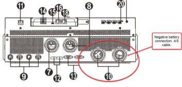
I think you need to start over and review his documents on grounding and the LV6548. No, you would not put a ground between your battery negative terminal and your panel. The only place you'll connect your negative terminal on the battery is to the negative battery input on the inverter. If you have a shunt it would go inline between the battery and the inverter. Your positive battery cable should also go to the inverter with a Class T fuse inline on it. Check the manual on all the connections.

Your panels should have a ground wire connected to the frame of each, I attached mine with lugs made for that purpose. The ground wire should connect to wherever your N-G bond is made. This ground wire is not showing in the drawing you posted from @FilterGuy but I'm pretty sure he has other drawings which include it.

Yes, you could connect another 3s2p string to the second MPPT on the LV6548. Maybe take some pictures of your setup and post them before you fire everything up.

1689871868051.png

1689871988167.png
 
After this, my array will be 4S2P. I would like to put the four additional panels on the other side of the roof (facing North). However, I am limited here b/c of the following:

Potential Problems:
1. I cannot connect 5 panels in series as the LV6548 is 250V per MPPT and if I connected 5 in series, I would be above this. Also, as these additional panels are facing away from the sun, I wouldn't want them connected in series to the panels facing the sun.

You can't do 5s2p due to voltage. How about 4s3p? Add an in-line fuse for each string.
(I don't understand why you said 4 additional panels, and configured as 5 in series. If you have 12 panels, 5s doesn't make sense.)

It is ok if you make 4s1p facing away from the sun and connect it in parallel with 4s2p facing the sun. Voltage will be similar, current is different.
Sorry...my bad. I agree that 5s doesn't make sense with 12 panels. I'm thinking I had some reason for indicating that before, but right now the reason escapes me.

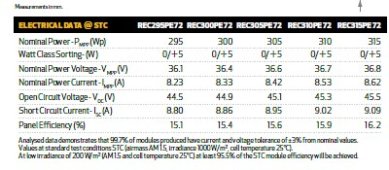
With the LV6548, I don't believe I can do 4S3P. The short circuit current is 9.02 amps. I'm using the Rec Peak Energy 72 series 310W panels.
rec 72 series electrical data.jpg
The MPP manual never lists going 3P with any of their examples, and although I've seen reports of going up to 25A in current being OK'd by MPP Solar, this would be higher than that. However, if it WAS possible, that would be an absolutely awesome way to do it and comparatively easy, assuming that my 10 gauge wire over approximately 50 feet distance can handle that amperage.
 
Sorry...my bad. I agree that 5s doesn't make sense with 12 panels. I'm thinking I had some reason for indicating that before, but right now the reason escapes me.

With the LV6548, I don't believe I can do 4S3P. The short circuit current is 9.02 amps. I'm using the Rec Peak Energy 72 series 310W panels.
View attachment 158463
The MPP manual never lists going 3P with any of their examples, and although I've seen reports of going up to 25A in current being OK'd by MPP Solar, this would be higher than that. However, if it WAS possible, that would be an absolutely awesome way to do it and comparatively easy, assuming that my 10 gauge wire over approximately 50 feet distance can handle that amperage.
The LV6548 starts clipping at 17 to 17.5 amps. You're going to have that even with 4s2p.
 
LV6548: "Max PV Input Current 18A (each [of 2 inputs])"

I don't know if that is 18A Imp or Isc. Either way, with 9.02A Isc for a panel, you're OK at 2p.

If I had panels with 13.5A Isc and could make two strings with 90 degree angle between them (13.5 x 2 = 27A), I'd expect the presented area to be 1/sqrt(2) as much, about 18A, so I'd do it.
With 3 strings you can't do as well. But with 2 strings same orientation and 1 string different, it could be 25A. Check roof angle and do a bit of trig.

Check with the manufacturer (or manual) and see if over-paneling this much is OK. So long as inverter won't hurt itself, it will just clip.

10 awg has ampacity 40A, but NEC only allows 30A. And you're supposed to design OCP & wires for 1.56x Isc (I'm not sure if you can do 1.25x with no OCP.)
You would have fuse per string, but no need for home run wire to be fused.

Distance is only voltage drop. You can calculate whether it would approach minimum operating voltage. 50' isn't much, not likely a big deal.
 
If I had panels with 13.5A Isc and could make two strings with 90 degree angle between them (13.5 x 2 = 27A), I'd expect the presented area to be 1/sqrt(2) as much, about 18A, so I'd do it.
With 3 strings you can't do as well. But with 2 strings same orientation and 1 string different, it could be 25A. Check roof angle and do a bit of trig.
I'm confused here as you're talking over my level of knowledge (not difficult to do, lol).

Would you be willing to direct me to where I could read more about how to calculate the angles between strings having an effect on the amps?

I know that I want all panels in a single string to be facing the same way. Two different strings pointed in different directions can be in parallel. In the case you were discussing previously, I would have two strings of four panels in series facing one direction, and one series string facing a different direction. Each string would be connected in parallel. Hopefully this makes sense.

If I understand correctly, because strings are facing different directions, it could never happen that all three strings are at max amps at the same time. So, it's not as simple as multiplying the max amps by 3 to get the total theoretical current.

Just to be clear on what I'm looking at then, my garage roof faces north and south. I currently have 6 panels on the roof facing south. I would put two more on the wall (perpendicular to the ground) facing south. Those 8 panels would be two series strings connected in parallel. Then I'd have 4 panels on the north side of the roof (again connected in parallel to the other two strings). The angle of the roof is 30 degrees.

thank you for your help!
 

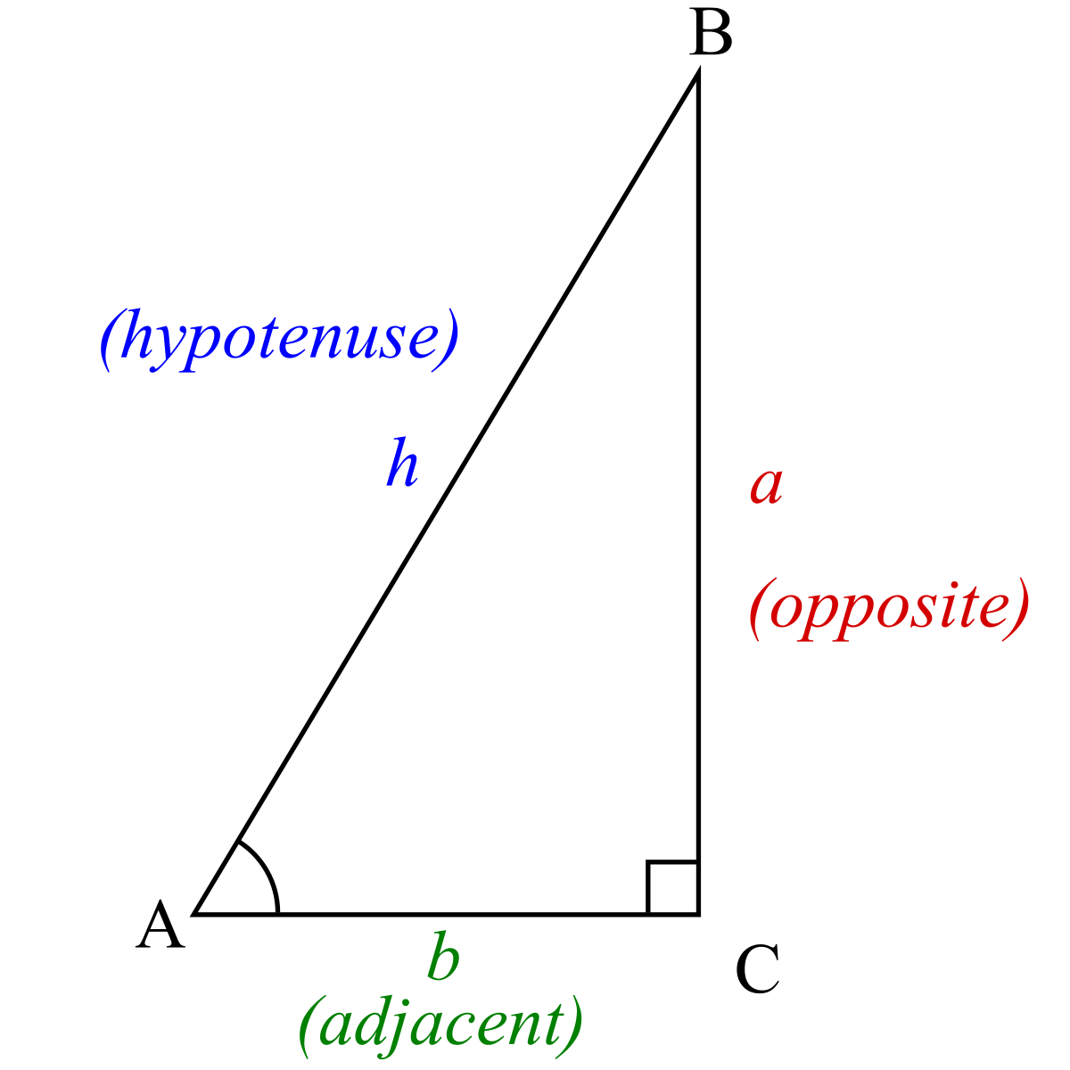
If angle is 90 degrees, and even if length of legs aren't equal, hypotenuse h = sqrt(a^2 + b^2)
If other than 90 degrees, you can evaluate with trig somehow, maybe draw a line from a point of triangle so perpendicular to opposite side.

Determine how long that line is from far edge of one string of panels to far edge of the other. Multiply by length of string. That gives area presented to the sun, how much energy it can capture. Ratio of that area to total panel area should be a decent approximation of array output.

Similarly, your roof has an area of shingles (ignore any eves) that is greater than square footage of house. That smaller area of the house is what we're estimating.
 
Last edited:
LV6548: "Max PV Input Current 18A (each [of 2 inputs])"

I don't know if that is 18A Imp or Isc. Either way, with 9.02A Isc for a panel, you're OK at 2p.

If I had panels with 13.5A Isc and could make two strings with 90 degree angle between them (13.5 x 2 = 27A), I'd expect the presented area to be 1/sqrt(2) as much, about 18A, so I'd do it.
With 3 strings you can't do as well. But with 2 strings same orientation and 1 string different, it could be 25A. Check roof angle and do a bit of trig.

Check with the manufacturer (or manual) and see if over-paneling this much is OK. So long as inverter won't hurt itself, it will just clip.

10 awg has ampacity 40A, but NEC only allows 30A. And you're supposed to design OCP & wires for 1.56x Isc (I'm not sure if you can do 1.25x with no OCP.)
You would have fuse per string, but no need for home run wire to be fused.

Distance is only voltage drop. You can calculate whether it would approach minimum operating voltage. 50' isn't much, not likely a big deal.
These inverters actually clip at a little over 17 amps. I know the specs say 18 but you know how specs are. When it's hot outside you're going to lose a little production but probably only 5% or so.
 
Don’t worry, you’re in good company lol. He seems to do that to a lot of people. But as I keep reading his comments over the months, more and more of what he says starts to click.
Same here. It used to give me a headache. Now it's just a dull throb. I think that's from knowledge finally soaking in.

1689911957525.png
 
I just heard back from the distributor of the LV6548. Ian. He indicated:
"3P is a bit much, the unit has 2 pv inputs, so 4s2p is max per input. As its rated input is 18A"
 
3P only too much if too much current. I have some 5A panels, so 3P would be less than 18A.
18A, you've already noted, somebody was OK at 25A. So long as the inverter doesn't draw more current than it can handle, it won't hurt itself. But some might.
Some inverters have reverse polarity diode across PV input, to protect against backwards connection. That would be harmed to excessive Isc.

I sometimes take rules and specifications under advisement.
 
I sent a response email to Ian regarding this. I informed him that some of the panels were in different directions and so true theoretical total amps would not be hit. I asked him if going over 18A is harmful for the LV6548 or if the excess amps are simply clipped.

He indicated that the amps are simply clipped as long as it's not too much over 25A.
 
I have another question for this and it's regarding grounding.

Right now I have a 10 gauge grounding wire connected to the solar panels using the Iron Ridge grounding lug. That is a continuous wire (well, except where I had to cut it to ground metal boxes before continuing on). It heads from the solar panels to the grounding bar on my main panel.

With the addition of more panels, can I branch off from that one grounding wire to ground the other panels or does it have to continue in one continuous path.

For example, I have the panels on the roof of my garage. The grounding wire right now comes through the inside of the garage, along the rafters, and through the roof to attach to the solar panels. Could I add a junction box inside the garage for the grounding wire and have one wire continue going to the solar panels on the roof and another grounding wire to the outside wall where I'll be placing some of the panels? In other words, with the grounding wire, can I have one wire going into a junction box and then have two coming out to different sets of panels?

Hope this makes sense. Thank you.
 
Back
Top