saracatlee
New Member
- Joined
- Jul 19, 2022
- Messages
- 4
[edited]
Last edited:
Use a Victron shunt for the DC side, and an Emporia Energy monitor for the AC side. Very simple, no hacking, easy to install.I know this is a massive thread, and perhaps someone asked this earlier, but I'm curious if anyone is tracking the load on their battery/inverter somehow. As I am not using the Load pins on my SCC, I can't track the battery consumption from there. I'm currently using a dumb power meter on the AC out on my inverter, but I'd like to get that into these grafana graphs instead.
You should only need the basic lower cost unit for your inverter. The 16 sensor unit is an awesome tool to discover your energy usage per line in your home, which can be used to calculate your energy consumption per month for your major appliances. The software provides a second by second update. I used that info to get a good understanding of my two Trane 3 ton HVAC units, along with overall consumption. I found that each unit pull around 2KW when starting, but drop down a bit while running. My total daily consumption was under 5KW peak. That made me feel comfortable using two MPP LV6548's for 13KW available.Whoa, the Emporia monitor with 16 sensors is on my WANT list now, thank you!
I'll likely grab the 16 for my panel, and the smaller one for my inverter. Thanks!You should only need the basic lower cost unit for your inverter. The 16 sensor unit is an awesome tool to discover your energy usage per line in your home, which can be used to calculate your energy consumption per month for your major appliances. The software provides a second by second update. I used that info to get a good understanding of my two Trane 3 ton HVAC units, along with overall consumption. I found that each unit pull around 2KW when starting, but drop down a bit while running. My total daily consumption was under 5KW peak. That made me feel comfortable using two MPP LV6548's for 13KW available.
Tex, you are doing EXACTLY what I am planning, but with LVX6048WP's instead. I have two SMA's currently connected to LG panels, and that has been working Flawlessly since 2004. I cannot monitor them, since they are so old.Hi Barkingspider
you are really making a great contribution here, thanks
looking for any advise you may offer
I have both off grid and grid tie systems
my raspberry pi 4 lit is about to be delivered today
I currently use Solar Assitant for the off grid system with 2 mpp lv6548 inverterss and 6 eg4 batts
I am also using emporia vue to monitor all cicuits, both on the off grid and on the grid
I am thinking about using home assustant on the new raspberry
would you recommend using the home assistant OS or load the raspberry OS ?
both Solar Assistant and emporia have some type off intergration with home assistant
my gridtie system is SMA using the sunny portal currently
I really like your dashboards better than any I have seen
I am far from a programmer type so wish me luck

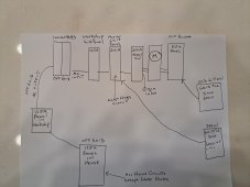
Is that a manual or auto transfer switch?here is a basic diagram of my systems
off grid is 2x mpp lv6548 with 6 eg4 batts
my electric meter is 400amp with 2x 200amp outputs avbl
gridtie #1 is 10 year old SMA 6000 with 6.44kw, no comm data readily avbl
gridtie #2 is new SMA6000-ua-41 with easy data access
I have 4 emporia vue systems located in all the panels. thats where I get data derived from the old SMA inverter which has no comms
View attachment 119221
I dont see a grid connection to the 125amp house panel. It looks like its only fed from the off grid inverters. Is that correct?its a huge 200amp manual transfer switch, I have it to be able to cut off all grid power to the main 200amp panel, for maint. and also if I want to run a whole house generator. we have a dual fuel 13k gen just in case.
in the workshop I also have a 60amp transfer switch between the inverters output and the 125amp panel in the workshop, so I can bypass inverters for maint. and still feed the house

Nice!here is a copy of a post I made recently to someone asking similar question..
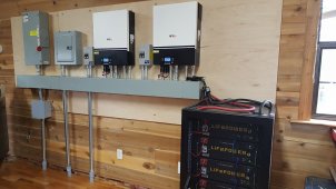
here is a pic of my system this is all in my workshop 100 ft from house
the AC in comes thru the left most conduit up from the floor. In the small junction box below the gutter and transfer switch I used morris split connectors to double each of the 4 wires. Then 1 set of AC input wires goes to the transfer switch and the other set goes to AC input on the inverters.
The AC output from the inverters goes to the transfer switch.
The transfer switch decides which power will go to the 125amp panel, located to the right of the transfer switch, which has the 60amp breaker going to the house panel
I did it like this so I could add some off grid outlets in the workshop at a later time
The middle conduit goin to the floor is the AC from the 60amp breaker going to the house
the conduit on the right is the incoming PV wires going to DC breakers before the inverters
View attachment 119249
Sorry for all the questions, but may I ask what make/model transfer switches you used? I am seeing prices over $1000 in some cases for a simple manual 240V switch.Nice!


