diy solar

diy solar

Off-grid Solar / Battery monitoring and control freeware

Yes I've looked through that thread and every other that comes up on a search for chargery here.
All you say is "connect using a simple USB interface with just RX/TX ports". Now you're saying there's 3 wires? Which port are you using on the chargery?
Plugging Red into Tx and Black into GND does not work, as suggested by Craig in his Chargery Communication thread.
Above you say Use RX/TX, can you please elaborate on this?

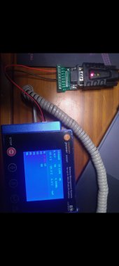
There are 2 wires coming out of COM3 on the Chargery BMS main unit. A red wire and a black wire.
1. Which of the 9 serial pins do you connect the red wire to.
2. Which of the 9 serial pins do you connect the black wire to.

Would really appreaciate a direct answer to those two questions, thank you.
I'm sorry. I'm away from my lab right now and just answering from memory. I'm back in April.
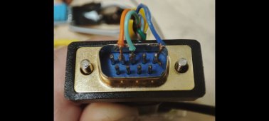
Your right, on the chargery it's just 2 wires. Rx and gnd. Rs232 comms are as is on any other project. Pins 2,3 & 5 on a DB5 I believe. Use Google.

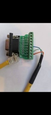
Screenshot_2022-03-08-21-59-46-880_com.google.android.apps.photos.jpg

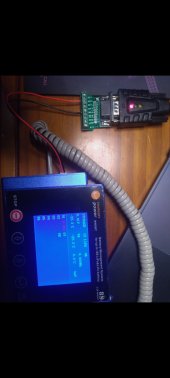
Screenshot_2022-03-08-22-02-01-012_com.google.android.apps.photos.jpg

You want to connect to Rx and GND. Above is an RS232 connection to a renogy wanderer 10amp device with RX and TX

Here is the photo i was looking for!

Screenshot_2022-03-08-22-08-21-515_com.google.android.apps.photos.jpg

Hope this helps!
 
Last edited:
Ahh yes!! Thank you. That connector pic is exactly the picture I was looking for.
Much appreciated. Looks like Black to GND and Red to RXD.
Now to go and try that combination.
Cheers
 
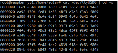
That did the trick! Now getting data, albeit with a fair bit of delay (i presume due to the heavy buffering).
1646803948613.png
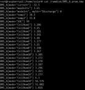
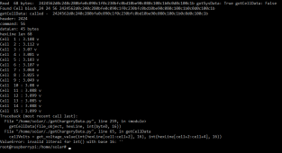
Ran the getChargeryData.py script and got an error. However it still output to /ramdisk and I was able to read the file!
1646804045284.png
1646804062593.png


Any idea what the error means? Sorry I don't know python at all. These are lines 65 and lines 259 of the file.
1646804158364.png
I have already changed 32 to 96.

1646804193517.png
 
Hmm it looks like your script is coded for V1.22. There has since been a few updates. Could the extra information now in the hex output be interfering with your script function?
Found a guy who makes python scripts for the chargery but for the venus OS. I presume it wouldn't be too hard to add the extra metrics using their script? I think I'll start watching some videos on basic python coding.


Here is the latest protocol I could find.
http://chargery.com/uploadFiles/BMS24T,16T,8T Additional Protocol Info V1.25.pdf
1646837075624.png
 
Last edited:
Ive got a 16s BMS, which is why I changed the code as advised.

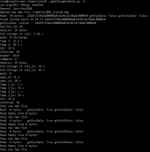
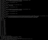
Here is the output of the script with debug mode:
1646863564661.png
1646863587013.png
 
So I changed the script, where it states to change to 96 for a 16s BMS. I changed it to 64 (since in the error in post above, it tries to read cell 17 and above). Now the script works well for about 5mins and I'm getting good data output to Grafana.
After about 5min, the script terminates in the same error.
1646865911793.png

Ran in Debug mode to try catch the error:
1646869162942.png
 
Last edited:
Looks like raw data for cell 16 voltage was corrupted. That points to a bad communication pipeline..

Check all the wires are connected firmly.

Run it a few times in debug mode and see if it always fails trying to decode cell voltage 16 and around the same elapsed time.

I have the same device and it has never failed.
 
Ok so I've been recording the fail times. It is anywhere between 3-20minutes. Seems like data is randomly corrupted. All wires connected well.
I've come up with 2 solutions. Struggling to code it, since I'm new to python.
1. Write a seperate script that checks if the getChargeryData.py script is running, every 10seconds. If it stops, then it restarts it.
2. Modify getChargeryData.py so that it loops back to start, if it encounters an error decoding the hex stream, rather than crashing.
 
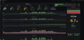
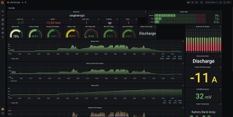
Success!! Everything working together!! Very happy with the great data its outputting already!
Thank you BarkingSpider for all the help and for writing this all up in the first place!
What an adventure it has been getting this to run, given I have no coding experience. Have spent the last 6 days installing the pi and its software and trying to get this all to work.
Next up, get data from the Deye inverter to the Pi and onto Grafana!

The getChargeryData.py script still crashing every 5min lol, no idea how to modify it. Instead I've written a little thing to make it restart when it crashes.
1646887842979.png
 

Attachments

  • 1646887815056.png
    1646887815056.png
    320.1 KB · Views: 32
Last edited:
Looks great! When i get home in April I'll take a look to see if i can find anything wrong with the script. Did it always fail reading and decoding the data for cell #16? This might be a clue. You will n need to run it in debug mode to find out.
 
Looks great! When i get home in April I'll take a look to see if i can find anything wrong with the script. Did it always fail reading and decoding the data for cell #16? This might be a clue. You will n need to run it in debug mode to find out.
All going well a few days later. Script just gets restarted whenever it crashes.
I'm absolutely loving the data metrics. Its already helped me identify one issue and modify my battery design slightly.

It fails reading between cells 14 to 16 usually. I've recorded a bunch of the fails and put it in a word doc. I'll msg them to you so you can have a look later.

Thank you for writing this wonderful piece of software, and the guide to install it all! I'd be keen to buy you a beer for all the help. Let me know if you have a paypal link or something.
 
So glad your finding it useful, all i can ask is that you help support the project by aiding others achieve the same goal you did. Also post any good tips you encountered to improve the installation process, and anything you add to it.

Have fun!
 
I have read nothing from the recent posts but I see people struggling w/ cables (as always).

So... the main issue I found with DIY cabling is that the Victron Brand cable is isolated and the one from the old video that everyone suggests following is NOT.

I updated what to do here: https://community.victronenergy.com/answers/119996/view.html
Step 2 is what you need.

SOLUTION! Get an isolated USB Serial adapter!
The serial adapter that is listed in MOST of the DIY VE.Direct cable tutorials is not isolated. The Victron cable is isolated. This leads to issues when trying to communicate with something like a shunt because you get ground loops. So... to (probably) not fry your stuff AND to get info from your shunts, try the below.
The original cables still work w/ my SmartSolar (for now). We'll see if that becomes an issue when I start actually using it for charging.
How I connected my BMV or SmartShunt to my VenusOS device:
  1. Replace the bad buck converter with a less-bad one.
  2. Get an isolated USB to Serial adapter.
    • I purchased this one. It's an "isolated FT232RL USB to TTL".
    • Use the included jumper to do a loopback test to confirm it's working.
      • Google will teach you how to do this w/ PuTTY.
    • Remove the plastic casing so it doesnt interfere with other ports.
    • I heat-shrinked mine with clear heat shrink.
    • It doesnt matter which voltage you choose because you wont use it. Leave the jumper where it is.
  3. Connect the adapter GND, TX, & RX pins to the Victron component the same way that one is instructed in all the other DIY cable tutorials. (Do not connect the VCC 5v or 3.3v to the Victron component, or else).
  4. Plug the devices in.
  5. Shazam!! You should have a working connection between your shunt and your VenusOS device.
This worked for me, it may not work for you.
Good luck!

TLDR: get isolated serial adapter.
 
All going well a few days later. Script just gets restarted whenever it crashes.
I'm absolutely loving the data metrics. Its already helped me identify one issue and modify my battery design slightly.

It fails reading between cells 14 to 16 usually. I've recorded a bunch of the fails and put it in a word doc. I'll msg them to you so you can have a look later.

Thank you for writing this wonderful piece of software, and the guide to install it all! I'd be keen to buy you a beer for all the help. Let me know if you have a paypal link or something.

Hmm it looks like your script is coded for V1.22. There has since been a few updates. Could the extra information now in the hex output be interfering with your script function?
Found a guy who makes python scripts for the chargery but for the venus OS. I presume it wouldn't be too hard to add the extra metrics using their script? I think I'll start watching some videos on basic python coding.


Here is the latest protocol I could find.
http://chargery.com/uploadFiles/BMS24T,16T,8T Additional Protocol Info V1.25.pdf
View attachment 86652

Well I did some rewirte of the code, you can select different Protocol versions:

https://github.com/TheSmartGerman/SolarShed

I added a CMD interface and checksum verifikation:

1648801278144.png

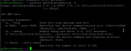
So you can call it like this:

'getChageryData.py -c 16 -P V126'

Cell Impedance Measurement is not working at the moment... Have to fix this.

Maybe it's a option to use µPython on ESP32 and send the data by MQTT
 
Can anyboy give me a advice for Grafana:
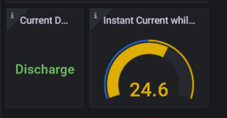
My charge/dischgarge protection is not shown properly:

1648803179224.png

I use the panel from joe. So it should show the status. It's configured to show the last "myStr" but it didn't worked yesterday.

Is it possible to change color too? Also if it goes from "Release" to "Protection" or int value from "0" to "1" change color / bgcolor? HOW is this done?

{ "id": 28, "gridPos": { "h": 3, "w": 3, "x": 14, "y": 0 }, "type": "stat", "title": "Charge Protection", "datasource": "Prometheus", "pluginVersion": "8.2.1", "maxDataPoints": 100, "links": [], "fieldConfig": { "defaults": { "thresholds": { "mode": "absolute", "steps": [ { "color": "green", "value": null }, { "color": "red", "value": 1 } ] }, "mappings": [ { "options": { "match": "null", "result": { "text": "N/A" } }, "type": "special" } ], "color": { "mode": "thresholds" }, "unit": "none" }, "overrides": [] }, "options": { "reduceOptions": { "values": false, "calcs": [ "lastNotNull" ], "fields": "/^myStr$/" }, "orientation": "horizontal", "text": {}, "textMode": "auto", "colorMode": "value", "graphMode": "none", "justifyMode": "auto" }, "targets": [ { "exemplar": true, "expr": "BMS_A{mode=\"chgProtectionInt\"}", "format": "table", "instant": false, "interval": "", "legendFormat": "Work Mode", "refId": "A" } ], "cacheTimeout": null, "description": "", "interval": null, "timeFrom": null, "timeShift": null }
 
Still struggling with the update of the Grafana string, any ideas:

1649063154162.png

1649063183664.png

Current is ok, but the myStr is not updated...

BTW. Got the impedance readout fixed - well sort of... I get data, caluclations seems to be ok. But comparison between the readout data and shown on the BMS Display seems not to match.

If anyone is interessted I can commit my acutal code to github...
 
Back
Top