diy solar

diy solar

Open circuit battery in a series string while midpoint connected to a battery in other string: how much current will flow?

m0onspell

New Member
Joined
Oct 18, 2022
Messages
139
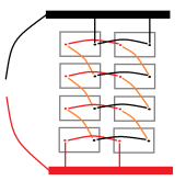
In one of Victron's manuals it shows how to use battery balancer with series-parallel battery bank:
1673222424303.png

It says:
In case of series-parallel connection, the midpoint interconnecting cables must be sized to at least carry the current that arises when one battery becomes open-circuited. - In case of 2 parallel strings: cross section 50% of the series interconnecting cables. - In case of 3 parallel strings: cross section 33% of the series interconnecting cables, etc.
I don't think I understand how to calculate that current. I tried to google but found nothing.
Is there any visualization/explanation for that kind of fault available?
 
I don't think I understand how to calculate that current. I tried to google but found nothing.
Is there any visualization/explanation for that kind of fault available?
This is a job for @Solarod ... hopefully this will conjure him.

This is one of his awesome threads on currents:
 
I don't think I understand how to calculate that current. I tried to google but found nothing.
It is not the total current that would change or need to be calculated, . What is possible is that total current across one of the packs that should determine the wire size. For example, if the total current is 150 Amps and you have three batteries in parallel, then if two battery BMSs disconnect then the remaining battery will carry the entire 150 Amps and the interconnects should be sized for 150 Amps. This scenario could happen during discharge or charging. During discharge the inverter is the load and during charge the battery is the load but the inverter determines the current based on how it is programmed.
 
Last edited:
It is not the total current that would change or need to be calculated, . What is possible is that total current across one of the packs that should determine the wire size. For example, if the total current is 150 Amps and you have three batteries in parallel, then if two battery BMSs disconnect then the remaining battery will carry the entire 150 Amps and the interconnects should be sized for 150 Amps. This scenario could happen during discharge or charging. During discharge the inverter is the load and during charge the battery is the load but the inverter determines the current based on how it is programmed.
Hmmm alright, let's try to go with an example. So we have 4s4p bank 12V bank, each battery is 100Ah.
1673295070629.png
I don't understand what do you mean by "total current"? In a series string max current will be 100A, given 4 parallel strings, - the max current for the bank will be 400A. Let's say we're pulling that 400A. Let's assume the load is equally shared by each string, so 100A per string. Then B1 battery trips open. What happens then?
 
Let's say we're pulling that 400A. Let's assume the load is equally shared by each string, so 100A per string. Then B1 battery trips open. What happens then?
When one BMS opens the total current gets distributed across the three remaining packs which means each pack is supplying 133 Amps. I have been bouncing between two similar threads so if I missed some context, my apologies.
Total current is just the total current of the inverter if it is creating a load or charging at a constant current, . If one bank goes open then the three remaining banks have to split the load. The initial question was with regard to the section outlined in Red. If I had such a pack I would size the interconnects for 400 Amps in your example. Your diagram looks more like a 4S4P pack. I am not familiar with the devices in that victron diagram. Are those twelve volt batteries, each of which has a BMS?
 
Last edited:
When one BMS opens the total current gets distributed across the three remaining packs which means each pack is supplying 133 Amps. If one bank goes open then the three remaining banks have to split the load.
Wouldn't it work the same way for this wiring
1673360411733.png
But I was adviced that this method is better. So something else must be going on here.

The initial question was with regard to the section outlined in Red.
Because it is a well-known company that explicitly brings attention to apparently the same problem. So I used their example to better explain what I mean, which is "parallel strapping" between series strings. Don't really know how to call, so using that term by @RCinFLA.
I am not familiar with the devices in that victron diagram.
They're irrelevant.
Are those twelve volt batteries, each of which has a BMS?
Yes.
If I had such a pack I would size the interconnects for 400 Amps in your example.
Well, that would be the easiest thing to do. But why though? Each bank is 133A. What is the current flow?
1673295070629-png.128763

What was the thing about 30%, 50% cross section in victron's manual?
I don't quite understand.
 
What was the thing about 30%, 50% cross section in victron's manual?
I don't quite understand.
I just assume it was something lost in translation. I do understand the concept of increasing current flow as cascading BMSs open for whatever reason, I also as far as risk management I am conservative so I plan for worse case.\As far as the connection topology, I don't disagree with @RCinFLA. My 3P4S 42kWh pack uses straps which I sized to be consistent with the 4/0 battery cables even though there is a 250 Amp circuit breaker at the inverter. I only have one BMS for the entire pack so I don't have the same issues. is this theoretical or do you actually have sisteen 12 volt batteries?
 
I just assume it was something lost in translation. I do understand the concept of increasing current flow as cascading BMSs open for whatever reason, I also as far as risk management I am conservative so I plan for worse case.\As far as the connection topology, I don't disagree with @RCinFLA. My 3P4S 42kWh pack uses straps which I sized to be consistent with the 4/0 battery cables even though there is a 250 Amp circuit breaker at the inverter. I only have one BMS for the entire pack so I don't have the same issues. is this theoretical or do you actually have sisteen 12 volt batteries?
I have 8, maybe will have 12. But my main goal is to clarify how the electrons flow through the batteries.

This is the page from my battery's manual that confused me
photo_2023-01-07_15-57-46-jpg.128313


I am trying to understand the path of the electons flow. Let's say we're charging with some current (200A) and that the battery Y tripped open:
1673474331734.png
So the electrons flow (follow the blue line) through the main pos conductor to the buss bar. From there the flow is divided equally to 100A between the two strings. Then the path is shown unti. the point where I am able to understand it, see two blue dots. Where does the flow goes from there?
 

Attachments

  • 1673473973052.png
    1673473973052.png
    9.1 KB · Views: 1
I have 8, maybe will have 12. But my main goal is to clarify how the electrons flow through the batteries.
I will try to explain in the context of the physics of electricity which I have learned over the years. There are Physicists and Ehgineers who argue over which way the electrons flow but for simplicity lets just refer to current from negative to positive through the load. Current will flow through the path of least resistance. Assuming the resistance of each of your 12 volt batteries is the same in the above diagram, then the current will be divided between the pair of 12 volt battery sets. If there is any difference then Ohms law can be used to see how much current will flow. That could change as total current increases and one cell may discharge slower than the other, in which case, current will flow between the parallel cells in an attempt to keep the voltage the same. If you are into the detail, there is a document on the Orion BMS site that describes this in detail. They call these Eddy currents, but some people say that is not the correct term. Whatever you want to call them, if they are significant they could trip one of the eight individual BMSs in one of those batteries. If that happens then that remaining 12 volt battery would be carrying the entire load and its interconnects and BMS capacity should be sized for the entire load or the interconnects will be overloaded and/or the remaining BMS will open and the entire pack will not work.
 
If that happens then that remaining 12 volt battery would be carrying the entire load and its interconnects and BMS capacity should be sized for the entire load or the interconnects will be overloaded and/or the remaining BMS will open and the entire pack will not work.
Can you please tell me in reference to the diagram where the current will flow when the battery Y trips open? And how much current?
I don't quite understand what is "that remaining 12 volt battery" as if one battery is open, there's still 7 of them.
 
Then the path is shown unti. the point where I am able to understand it, see two blue dots. Where does the flow goes from there?
When the BMS in battery Y opens, the black line between is broken between Y and the battery on the right, The 200 Amps can only flow though that one battery, then it may split at the top and each leg might carry 100 Amps. The big if is how the current might split after flowing through the single battery. It may be affected by the resistance of the red interconnect and the resistant of the next battery at the top. If that battery has less resistance then it will see more current and the left leg will see less current. There may be others that can explain that in more detail.
 
Last edited:
When the BMS in battery Y opens, the black line between is broken between Y and the battery on the right, The 200 Amps can only flow though that one battery, then it may split at the top and each leg might carry 100 Amps. The big if is how the current might split after flowing through the single battery. It may be affected by the resistance of the red interconnect and the resistant of the next battery at the top. If that battery has less resistance then it will see more current and the left leg will see less current. There may be others that can explain that in more detail.
First of all, thanks for bearing with me. You explain exceptionally well.

And I think that I've finally gotten it! Here's an updated diagram, I showed the interesting part of the flow with purple:
1673484283947.png
If that's right, then it is clear where 200A is coming from and which battery takes that load. Although looking at this I am concluding that interconnects should be able to carry 100A and not 200. Looking back at what Victron says:
In case of series-parallel connection, the midpoint interconnecting cables must be sized to at least carry the current that arises when one battery becomes open-circuited. - In case of 2 parallel strings: cross section 50% of the series interconnecting cables. - In case of 3 parallel strings: cross section 33% of the series interconnecting cables, etc.
I still don't understand what is "cross section 50%", "cross section 33%", but maybe that just means that those wires should be able to carry the full series string load? In case of 2 strings that will be 50% of the total current, 3 strings is 33% etc.
 
I'm putting that on my resume.
Did I get that right?
I showed the interesting part of the flow with purple:
View attachment 129149
If that's right, then it is clear where 200A is coming from and which battery takes that load. Although looking at this I am concluding that interconnects should be able to carry 100A and not 200.

I still don't understand what is "cross section 50%", "cross section 33%", but maybe that just means that those wires should be able to carry the full series string load? In case of 2 strings that will be 50% of the total current, 3 strings is 33% etc.
 
Did I get that right?
Ok I see your drawing now.

Unless I misunderstand your intent just get rid of the red and black laces.
As long as the busbars are sufficiently low resistance it doesn't really matter if you tap the load from opposite corners.
To clarify If the busbar is has enough beef the incremental resistance is just noise compared to the variability of the joinery resistance.
I won't have them, I just want to understand what is the current flow in such configuration when Y battery trips open. As an excercise.
 
Back
Top