diy solar

diy solar

Paralleling LifePO4 banks with...

400bird

Solar Wizard
Joined
May 23, 2020
Messages
3,691
Location
California
Thanks to a gracious member here, I just picked up 48 LifePO4 cells that I plan to build into three 16s batteries.

I had I initially considered retiring my current battery bank (14s NMC)

But, now I'm reconsidering...

Please, let's stay on track. Can we please not discuss everyone's fear in these cells? I really don't want to be told that you don't trust them and wouldn't want them in your house.
They are outside the house, 5' from anything. Inside a metal box, lined with cement board, with a WiFi smoke detector inside. They are well protected with a BMS, shunt trip breaker, and fuses.

Anyways

If I limit charge on the LifePO4 cells to 3.5 volts per cell, the NMC cells will be fine (reaching 4 volts/cell)
On the low end, of I stop discharging the LifePO4 at 2.8 volts per cell, the NMC will also be fine (reaching 3.2 volts per cell)

As you can see, with slight limits to each cell voltage type (leaving some capacity on the table) all the cells can be kept in a happy range.

Sure, each chemistry has a different discharge curve, so at times all of the load will be on the LifePO4 cells and other times it will all be on the NMC bank. But, each bank can individually handle the load (6kW) or charging (7.5kW)
Each bank is individually >30kWh, so the loads are a relatively low 0.23c max

Wow, that was a lot of back story, on to the show.

My question:
Once LifePO4 has finished charging it naturally settles from ~3.5-3.65 volts down to something in the 3.3-3.4 volt range over maybe 10-30 minutes. However, the NMC won't do this and will likely hold the LifePO4 pack up near the 3.5 volt/cell range.


Should I be concerned about this?
I have a contactor/relay rated to 800VDC/600amps that I could use to disconnect and rest the LifePO4 pack until the NMC pack voltage has discharged down to match the rested LifePO4 pack.

If you read all the way through this, thank you!
 
I wouldn't consider peak LFP charge voltages. Stick with ~3.40-3.45V as you can easily get to 100% if patient.

3.92V is a "sweet spot" of sorts for NMC @ about 75-80% SoC.

14S @ 3.92V/cell equates to a very nice charge level for 16S LFP @ 3.43V/cell. Takes awhile, but can get to true 100% and will do so "gently" optimizing cycle life.

So, I wouldn't hesitate to use a parallel NMC/LFP battery bank charging to 54.88V and discharge to 42V. FLoat at 54V - would allow the NMC to discharge a little.
 
My question:
Once LifePO4 has finished charging it naturally settles from ~3.5-3.65 volts down to something in the 3.3-3.4 volt range over maybe 10-30 minutes. However, the NMC won't do this and will likely hold the LifePO4 pack up near the 3.5 volt/cell range.


Should I be concerned about this?
I have a contactor/relay rated to 800VDC/600amps that I could use to disconnect and rest the LifePO4 pack until the NMC pack voltage has discharged down to match the rested LifePO4 pack
Yes. What is the total voltage of the NMC pack at 3.5v/cell? That is the voltage that the NMC will be "floating" the LiFePO4.

14x3.5=49.0
16x3.4=54.4

I think the LifePO4 will be floating the NMC.
 
Yes. What is the total voltage of the NMC pack at 3.5v/cell? That is the voltage that the NMC will be "floating" the LiFePO4.

14x3.5=49.0
16x3.4=54.4

I think the LifePO4 will be floating the NMC.

3.5V NMC is at about 20% SoC, so I think its reference was relative to the LFP cells not NMC. If the two are charged together to 16S 3.5V, the NMC will have a tendency to "float" the LFP.
 
I wouldn't consider peak LFP charge voltages. Stick with ~3.40-3.45V as you can easily get to 100% if patient.

3.92V is a "sweet spot" of sorts for NMC @ about 75-80% SoC.

14S @ 3.92V/cell equates to a very nice charge level for 16S LFP @ 3.43V/cell. Takes awhile, but can get to true 100% and will do so "gently" optimizing cycle life.

So, I wouldn't hesitate to use a parallel NMC/LFP battery bank charging to 54.88V and discharge to 42V. FLoat at 54V - would allow the NMC to discharge a little.
Good point, I hadn't thought about lowering the float!
Thanks for backing up my theory.

I also just realized that because I finish charging with my Midnite Classic charge controller, I can hook up their shunt and let it float based on current going into the LifePO4 bank. There will be some flowing to loads and to the NMC bank, but the end amps into the LifePO4 bank is what's important.
 
Yes. What is the total voltage of the NMC pack at 3.5v/cell? That is the voltage that the NMC will be "floating" the LiFePO4.

14x3.5=49.0
16x3.4=54.4
But, that's not how the math work. Each pack voltage will be constant. These are paralleled at the pack level , not cell level.

16 x 3.5 volts per cell = 56 pack volts = 14 x 4 volts per cell
Or
16 x 3.4 = 54.4 = 14 x 3.88

I think the LifePO4 will be floating the NMC.
I don't think that's the case.
 
I don't see huge problem.
Charge at 56V (4.0V for NMC and 3.5V for LFP) and stop discharge at around 46V (3.3V for NMC and 2.9V for LFP) and everything will work.
Considering the different discharge curve between NMC and LFP there will have different discharge current from batteries at different SOC, but that will work.
Still, your questioning about what happen at the voltage of a fully charge LFP cells when hook to the NMC is relevant. Is the LFP cells naturally dropping to 3.4V will discharge the NMC or the LFP cells will simply stay at 3.5V? I can't wait to know 😄
 
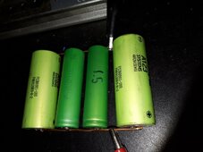
Ummm! Find the answer was tempting. I don't have NMC 18650 cells, but I have LiMn 18650 cells and 26650 LFP cells.
Both cells type have around 1.5Ah left. So I connect all them in parallel.
Sadly the discharge curve of LiMn cells is different than NMC as there is almost no energy left in the cells below 3.8V at low discharge rate.
But I took few minutes to tried.

I charged the 4 cells in parallel to 3.55V at 1A with 0.1A end of charge.
After I disconnect 1 LiMn cell and 1 LFP cell who will act as comparaison. So left 1 LiMn and 1 LFP in parallel.
Results tomorrow...

20240228_202144.jpg
 
Setting aside the hi/low voltage range match already covered.... some thoughts....

I'm guessing there will be some light stress as the NMC's discharge curve is a little higher (at hi SoC) and lower (at low SoC) whereas the LifePo4 is pretty flat - as you acknowledge. So the NMC will provide a bit more load at high end and LifePo4 a bit more at the lower end of the operational voltage range. However... unless the loads are extreme or the wiring is extremely thin this is not likely to be that worrisome operationally from reading some posts on others that have tried this.

Side comment to the above. A guy that experimented with this posted he observed the largest current movement when loads were removed - e.g. as the different chemistries try to go their respective rest voltages compared to the load voltage. Again, a large or extreme load change would make this behavior stronger compared to a modest load change.

Next, I wonder if there may be some level of stress (because of the uneven loading described above) that will shorten the life (number of cycles) a bit?. This may not be a concern in this case even if it's real.

Finally, one will likely need separate BMS - not sure there's any system that will allow for a single unified BMS. Again, this may not be a concern for you're situation.


Will be interested to follow actual results as you get them :)
 
Last edited:
Ummm! Find the answer was tempting. I don't have NMC 18650 cells, but I have LiMn 18650 cells and 26650 LFP cells.
Both cells type have around 1.5Ah left. So I connect all them in parallel.
Sadly the discharge curve of LiMn cells is different than NMC as there is almost no energy left in the cells below 3.8V at low discharge rate.
But I took few minutes to tried.

I charged the 4 cells in parallel to 3.55V at 1A with 0.1A end of charge.
After I disconnect 1 LiMn cell and 1 LFP cell who will act as comparaison. So left 1 LiMn and 1 LFP in parallel.
Results tomorrow...
Those are paralleled at the cell level, where the voltage ranges don't match up. But I would have 16 lfp cells in series paralleled with 14 regular lithium cells in series, the voltage ranges are compatible.
 
Setting aside the hi/low voltage range match already covered.... some thoughts....

I'm guessing there will be some light stress as the NMC's discharge curve is a little higher (at hi SoC) and lower (at low SoC) whereas the LifePo4 is pretty flat - as you acknowledge. So the NMC will provide a bit more load at high end and LifePo4 a bit more at the lower end of the operational voltage range. However... unless the loads are extreme or the wiring is extremely thin this is not likely to be that worrisome operationally from reading some posts on others that have tried this.
Good points, everything is wired in 0000 and 000, should be fine there.
The load will likely transition back and forth. First on the NMC, then LifePO4, then back to NMC.
But each chemistry will be set up to fully support all my loads without the other chemistry, so I don't see the shifting load being an issue.

Side comment to the above. A guy that experimented with this posted he observed the largest current movement when loads were removed - e.g. as the different chemistries try to go their respective rest voltages compared to the load voltage. Again, a large or extreme load change would make this behavior stronger compared to a modest load change.
I think this is my concern. The NMC doesn't relax much when the load is removed or charge stops. However, when the charge cycle is completely, the LifePO4 pack will want to drop about 3 volts while the NMC wants to hold steady.

I'll have separate current shunts on each pack, so I'll be able to monitor and report what really happen.
Next, I wonder if there may be some level of stress (because of the uneven loading described above) that will shorten the life (number of cycles) a bit?. This may not be a concern in this case even if it's real.

Finally, one will likely need separate BMS - not sure there's any system that will allow for a single unified BMS. Again, this may not be a concern for you're situation.
I'm running Batrium on the NMC. My hold up right now is deciding if I want to run another Batrium set up on the LifePO4 or something different.
Will be interested to follow actual results as you get them :)
I'll definitely be posting updates as them happen.
 
Those are paralleled at the cell level, where the voltage ranges don't match up. But I would have 16 lfp cells in series paralleled with 14 regular lithium cells in series, the voltage ranges are compatible.
Yes, I know. Still my test is relevant as you want to know (we want to know 😄 ) if LFP cells will drain energy from NMC cells when they pass from full charge voltage to resting voltage (generally from 3.5 - 3.6V at 100% SOC to 3.3 - 3.4V at 100% SOC).
 
Results tomorrow...
And the answer is... no!
No, the LFP cells, at 100% SOC, will not drain NMC cells in an arrangement 16S vs 14S.
When hook to NMC cells in parallel, the LFP cells will simply stay at higher voltage up to when discharge will start.

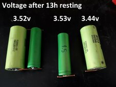
Here is the voltage of my test after 13h.
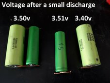
And to push further the test, I discharge a bit each cell at 1A for one minute for single LFP and LiMn cell and 2A for one minute for the parallel LFP/LiMn cells.
Resulting voltage on second picture.

20240229_095011.jpg20240229_095011_discharge.jpg
 
This kind of makes me wonder how it would go paralleling
some other cells with my 10s 36v NMC battery packs.

Definitely some interesting information in this thread.
 
Batrium on the NMC.

I'm open to suggestions on the LifePO4. I'm leaning towards another Batrium set up, but haven't decided.

Love Batrium, but once I deploy the second half of my battery on an MM8, I'm done with them.

I played around with a RPi running Venus OS running VRM with a JBD BMS and the dbus-serialbattery driver... wicked awesome...
 
Love Batrium, but once I deploy the second half of my battery on an MM8, I'm done with them.
I'm torn on that. I like using an external shunt and shunt trip breaker (vs running current through the BMS) it's got WiFi and I can get data into my other stuff.
I played around with a RPi running Venus OS running VRM with a JBD BMS and the dbus-serialbattery driver... wicked awesome...
I don't have any Victon equipment, so I don't know if that part would help me. If you've got links, I'll read about the set up.
 
Once LifePO4 has finished charging it naturally settles from ~3.5-3.65 volts down to something in the 3.3-3.4 volt range over maybe 10-30 minutes. However, the NMC won't do this and will likely hold the LifePO4 pack up near the 3.5 volt/cell range.
Should I be concerned about this?
Did you have other concerns except that what happened to LFP full charge voltage when connect to NMC?
 
Back
Top