diy solar

diy solar

Polarized breaker wiring

Zerpersande

New Member
Joined
Oct 5, 2022
Messages
80
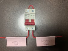
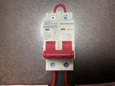
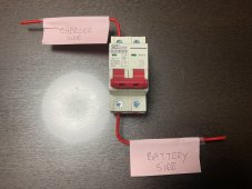
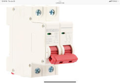
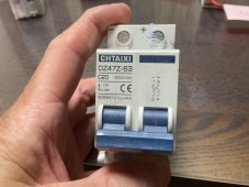
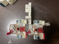
I want to put a 16A polarized breaker in the positive wire from my Victron IP22 12V/15A battery charger to my 12V 230Ah LiFePO4 battery. Partially for protection and partially to isolate it when not in use. I’ll (usually) only be using this to juice up my battery enough to get by during rainy periods. Will the wiring in the pics both isolate the charger and protect the circuit? Would it be better to wire the return from the battery in the top and out the bottom rather than use the loop?
 

Attachments

  • IMG_3324.jpeg
    IMG_3324.jpeg
    278.3 KB · Views: 10
  • IMG_3325.jpeg
    IMG_3325.jpeg
    232.2 KB · Views: 9
No real reason to need a breaker between charger and battery. You isolate the charger from the power side by either its on switch or a plug. If hard wired the line could have a fuse or breaker.

If for some reason you want to have a breaker on the battery side disconnecting the positive wire just one side of that breaker would be sufficient. Wire in from the top and to the battery on the bottom.
 
If for some reason you want to have a breaker on the battery side disconnecting the positive wire just one side of that breaker would be sufficient. Wire in from the top and to the battery on the bottom.
So this configuration?
 

Attachments

  • image.jpg
    image.jpg
    268.8 KB · Views: 8
Th
If for some reason you want to have a breaker on the battery side disconnecting the positive wire just one side of that breaker would be sufficient. Wire in from the top and to the battery on the bottom.
This would jibe with this other photo I found on Amazon of this breaker but with +/- indicators Included on the diagram. But similar breakers with the same diagram have different polarities for the same schematic.
 

Attachments

  • IMG_3326.png
    IMG_3326.png
    525.7 KB · Views: 4
  • IMG_3327.jpeg
    IMG_3327.jpeg
    209.6 KB · Views: 5
Also, I have 6 of these. I would gladly sacrifice one and open it up if it will ABSOLUTELY determine the polarity and proper wiring of these breakers. I’d also do it for shits and giggles anyone thinks it would be a useful pic to have in discussing posts regarding polarized breakers.
 
Also, I have 6 of these. I would gladly sacrifice one and open it up if it will ABSOLUTELY determine the polarity and proper wiring of these breakers. I’d also do it for shits and giggles anyone thinks it would be a useful pic to have in discussing posts regarding polarized breakers.
I love seeing the innards of stuff like that. Could be useful.
 
May not be always required. But if wiring a breaker marked for pos/neg as you show in your second image than wire it as marked when going from line to load. Positive in at the right top and back out at the right bottom. Those not marked anywhere for pos/neg are generally considered to not be polarized.

One other item is mounting orientation for the breaker is vertical. Not upside down or horizontal. This (I have been told) is to facility arc being drawn up into the arc chutes.
 
Last edited:
One other item is mounting orientation for the breaker is vertical. Not upside down or horizontal. This (I have been told) is to facility arc being drawn up into the arc chutes.
I thought the arc extinguisher was on the bottom. But I guess it would depend on which side. At least that’s the way this clip makes it seem.
 
I thought the arc extinguisher was on the bottom. But I guess it would depend on which side. At least that’s the way this clip makes it seem.
Interesting clip but his breaker orientation seems to be line in at the bottom, load out the top. Hard to make out if the switch lever is on or off in the image.
 
Interesting clip but his breaker orientation seems to be line in at the bottom, load out the top. Hard to make out if the switch lever is on or off in the image.
Yeah, it does seem to be line in at the bottom. Thing is though I have 3 or 4 other breakers of similar design and model number and their schematics are the same but the +/- are all like the one in this photo. I would think the schematic would result in the same wiring pattern.
 

Attachments

  • IMG_3327.jpeg
    IMG_3327.jpeg
    209.6 KB · Views: 3
I guess you would have to see the internals of both to see if they were similar or different.
 
Wiring with jumper across top will facilitate extenguishing the arc in the event your assumption of highest potential or cause of fault is reversed. If used as disconnect only no problem wiring through just one side. For best protection of circuit against faults, wire in and out bottom with suitable jumper across top terminals. Covers potential (flow) from either direction that way.
 
Wiring with jumper across top will facilitate extenguishing the arc in the event your assumption of highest potential or cause of fault is reversed. If used as disconnect only no problem wiring through just one side. For best protection of circuit against faults, wire in and out bottom with suitable jumper across top terminals. Covers potential (flow) from either direction that way.
Wouldn't the jumper be on the bottom? Line in from either potential source at top.
 
Really doesn't matter top or bottom. Key is jumper protects "flow" polarity from either direction. A polarized DC breaker is designed to extinguish arc in one direction...thus "polarized". If flow is from - to + pole it may be less efficient or totally ineffective at extinguishing arc as design is for + to - flow. Because DC never goes to 0 volts on its own in circuit like AC, 2 pole polarized breakers can provide disconnect and fault protection to circuit. Look at OP's first pic. Picture flow of current from left to right. In this situation the left pole of breaker may or may not extinguish arc as current is flowing opposite of design...however after jumper at top...current is now flowing through right pole as designed and should extinguish arc. Reverse current from right to left and left pole is disconnecting as designed. All this ASSUMES you are within the AIC ratings of breaker selected for maximum potential fault of circuit.
 
Opening breaker to interrupt charging, it experiences a small voltage.
Opening it if battery shorted (or BMS open and load prvides a short), it experiences full voltage.
Opening due to overload if SCC short, battery dumps short-circuit current into it. (This is the polarity recommended by vendors of polarized breakers.)

I favor non-polarized breakers (or fuses) for potentially bidirectional applications.

With one (+) and one (-) on each end, wiring across either top or bottom is just putting them in series, both in same polarity.

I would wire diagonally, from say (-) to (-). Connect one (+) to SCC and one (+) to battery. That way, whichever direction current flows, one of the poles has correct polarity to extinguish arc.
 
Here you go. This is the teardown of the 16A shown in the OP. As can be seen, the polarity marks on the terminals are NOT of the wiring schematic of this breaker. I used the markings from a breaker on Amazon with all of the same identifying markings BUT it had the polarities in the schematic. (See second pic)

To me this makes sense if you use the breaker for both lines in a circuit. Or for a single wire on just one side. (ASSUMING you can figure out the +/- positions. But this doesn’t make sense to me when using a jumper across the top for a single wire.

I think I am going to have to sacrifice a 63A breaker. I’ve decided that for my solar panel cutoffs I’m going to go with what appears to be a non-polarized DC on Amazon. (See third and fourth pics)

NOTE: Thanks very much to everyone contributing to this thread. I’m putting this in a can conversion so will be sleeping with my head within 3 feet of this setup. I have a vested interest in making sure this is done correctly. ?
 

Attachments

  • IMG_3328.jpeg
    IMG_3328.jpeg
    425.4 KB · Views: 11
  • IMG_3326.jpg
    IMG_3326.jpg
    75.8 KB · Views: 11
  • IMG_3329.jpeg
    IMG_3329.jpeg
    498.4 KB · Views: 9
  • IMG_3330.jpeg
    IMG_3330.jpeg
    606.8 KB · Views: 10
Picture flow of current from left to right. In this situation the left pole of breaker may or may not extinguish arc as current is flowing opposite of design...however after jumper at top...current is now flowing through right pole as designed and should extinguish arc.
Yeah, I can see that. But the breaker that did NOT extinguish the arc is now in danger of bursting into flames. What certainty is there that such doesn’t happen by the time the second breaker turns off the current?
 
Sounds like seven(7) of those non-polarized breakers would pretty much cover my system. Both lines coming from the solar panels, both lines into, and out of, the inverter and a single one on the charger positive because when use the charger I’ll disconnect everything other than power to my 12V bus box.
 
Back
Top