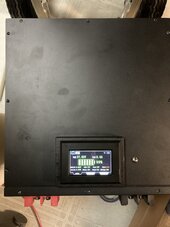
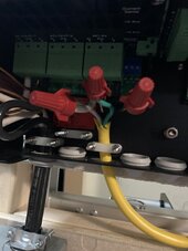
Good observation. There is actually a 2 inch plus gap there. Plus I am currently planning on placing hardiboard between the frame and battery.I'm concerned that the battery terminals line perfectly up with the dolly frame.
Looks like an accident waiting to happen.
You are using an out of date browser. It may not display this or other websites correctly.
You should upgrade or use an alternative browser.
You should upgrade or use an alternative browser.
Portable Victron Power Station operational
- Thread starter JJJJ
- Start date
I know it is being done and has been discussed in other threads. I have chosen to keep these upright for a multitude of reasons that exceed the scope of this tread.Yeah I'd be thinking of going vertical, panel up.
As a professional my favorite saying is "safety first". Something I never see discussed with portable dolly systems is insulating the metal frame. It is probably OCD but I saw this product and it got me thinking. Even if I decide to turn the battery back the other way, this product may still have some benefits either for this project or in the future:
Long story short, will be repositioning battery terminals in front. After a good nights sleep and getting a third opinion decided safety should be first consideration. Perhaps if this was another dolly design. Will probably run electric lines on top of battery in raceways. This will also counterbalance better since the battery weights will centered closer to the dolly.
Will show more later but will be revising the sides of the battery box to 2x6. This will provide additional lateral support.
Will show more later but will be revising the sides of the battery box to 2x6. This will provide additional lateral support.
These photos are very similar to before. There were a couple of updates for strength of the battery box. The side panels are now 2x6 material. In the back corner by the dolly the joints are secured with a quality indoor outdoor wood glue and timberlock lag bolts.
I replaced the 2x4 over the tongue with a 2x6. The battery terminals are back in front. Agree with the concerns indicated earlier. Perhaps if the dolly was a different construction alignment.
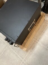
I replaced the 2x4 over the tongue with a 2x6. The battery terminals are back in front. Agree with the concerns indicated earlier. Perhaps if the dolly was a different construction alignment.

Still saving the funds up to purchase the Multiplus II. Hard to be patient at times.
Excellent recommendation earlier is to keep things simple. I am currently planning on constructing a simple lightweight wood frame that can be quickly attached to the frame of the dolly. It will support the bus bars (which will hold the battery fuse) and allow possible charge controller input in the future), UL rated outlets, shunt, small load center and the Multiplus II. Prior to attaching it I will give it a coat of intumescent paint which I have from a previous project.
Envisioning placing the Multiplus II higher on the frame. This will create a counterbalance for the battery pack and will allow leverage to work in my favor.
Last edited:
Sorry for the radio silence. Was saving up the $$ for the next purchase. Next thing I know I was replacing a kitchen sink and remodeling one of the bathrooms. Wife has been patiently waiting during my solar projects and it was time to update some things. Time well spent and she is happy which is the important thing.
Just placed a purchase from Current Connected for the Multiplus II 24v, Charge controller, BMV-712 shunt and some cable. @HighTechLab was very impressed with James. His approach was easy going, very helpful and honest. He steered me away from something which would not fit my system. That was very much appreciated.
The purchase process was very straight forward and painless. Hoping to post more once things arrive.
Last edited:
Brucey
Solar Wizard
Which charge controller did you go with?
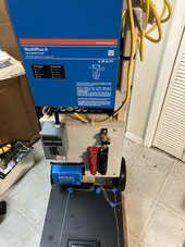
OK. Mounting frame has been built and attached to dolly. Facing covered with 1/4 inch Hardiboard. The Multiplus II has been mounted. Placed at the top to help counterbalance the battery pack. The string on the top of the battery box is where raceway will be placed to house the wires. The goal here is to find a framework which will enable the battery lines to be the same length.
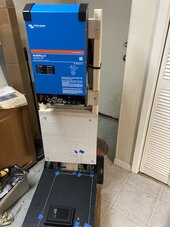

Starting to wire things together. Very appreciative to @HighTechLab for their video on wiring the Multiplus II. Moving 6 awg wire is a challenge at best. The technique described made the task so much easier. Thank you again!
HarryN
Solar Enthusiast
Looks like you are doing a great job on it.
One way to help bend wires a bit easier is to slightly warm them with a heat gun first. Don't over do it, but when you warm up the jacket slightly, it allows the strands inside to slide around a bit more. Bend it into place and then put the terminal on, as the strands will stick out at an angle vs straight and need to be trimmed up.
One way to help bend wires a bit easier is to slightly warm them with a heat gun first. Don't over do it, but when you warm up the jacket slightly, it allows the strands inside to slide around a bit more. Bend it into place and then put the terminal on, as the strands will stick out at an angle vs straight and need to be trimmed up.
Have breaker box wired in. Still need to connect outlet strips. Still trying to attach the AC input. It is 12 awg, tried doubling it but it won’t hold in the tension inputs. That was one of the advantages of the Multiplus, it had screws to hold things together.
Still need to run the wire from the battery. While the bus bars look fairly close there is a pretty good gap between the actual conduction bars. I might separate them a little more.
Also there is a gap between the battery and the dolly to allow air flow below and above the charge controller.
Many thanks to @timselectric for taking the time to inspect and critique my electrical work in the breaker box.

Last edited:
Brucey
Solar Wizard
Going to do something like an Anderson quick connect for the solar input?
Its a thought. Will probably update my portable solar panel to input to this unit.Going to do something like an Anderson quick connect for the solar input?
timselectric
If I can do it, you can do it.
- Joined
- Feb 5, 2022
- Messages
- 18,623
Use a short piece of #8 and connect it to the #12 in the connection area.
Hmmm. I could use a step down butt connector to do this. Would contain the wire to the multiplus box area. Otherwise would need a junction box with input output clamps so I could merge 12 awg with the 6 awg I already have.Use a short piece of #8 and connect it to the #12 in the connection area.
timselectric
If I can do it, you can do it.
- Joined
- Feb 5, 2022
- Messages
- 18,623
Or a wire nut, for simplicity.Hmmm. I could use a step down butt connector to do this. Would contain the wire to the multiplus box area. Otherwise would need a junction box with input output clamps so I could merge 12 awg with the 6 awg I already have.
Either way is fine.
Similar threads
- Replies
- 8
- Views
- 372
- Replies
- 1
- Views
- 445
- Replies
- 0
- Views
- 78


