diy solar

diy solar

Putting together my first system - Updated 4.16.22

ss2nv

New Member
Joined
Feb 12, 2022
Messages
12
I am piecing together a "solar generator" with which I intend on running two deep freezers (one with a defrost cycle), one full size fridge/freezer, and one small dorm-sized fridge. We live in the suburbs and are on the grid, so this will be for power outages only. I have a Kill-a-Watt and was going to plug in each one for a few days to get some KWh numbers to see what I needed as far as sizing... Well that didn't happen and I decided to haul off and start buying stuff instead.
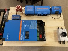
Below is what I have so far:
unnamed.jpg
IMG_6684.jpg
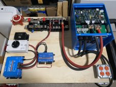
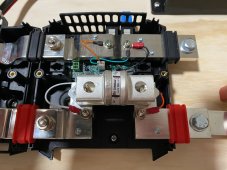
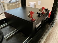
The Victron Power In will be modified to use Mega fuses. I need to decide on panels and some sort of disconnect for them. I also will be buying two of the SOK 206AH batteries to run in parallel instead of the single 100AH that I initially bought.
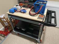
I want all of it to be portable, so I am putting it on a Rubbermaid cart. I still need to buy a piece of plywood to mount everything to, but it will be laid out basically like you see it, unless someone has any better ideas. Batteries will be on the bottom of the cart, obviously.

Let me know what you think. Ideas on panels? I am thinking about a way to attach a mount to the side of the cart to hang them on for storage. Maybe hang an extension cord reel on the end for the solar cabling... Not really sure, but love to hear some feedback!

Seth
 
Last edited:
...Let me know what you think.... love to hear some feedback!
  • Don't block the air inlets on the inverter (can't tell from the top-down image, but look's like the cart's lip might be covering them up when pressed against it)
  • Good job with the T-Class fuse and getting a CE approved switch (that's a bad spot to skimp). You might want a DC breaker in there too, something that will trip before the fuse (mainly because the fuse is expensive to replace).
  • Resistor pre-charge circuit?
  • What all do you want to know about your system (e.g., How will you monitor the state of your system? ) It looks like the shunt will give you SoC and the Victron 100/50 will give you solar watts, Do you need to know anything about AC charging or AC output?
  • Watch Will's video on how to make a proper crimp.
  • Where is the AC out on the Renogy? Make sure it's easy to get to (e.g., enough space to plug stuff in) and that the reset button (if manual) is easy to get to.
  • Make boots for exposed terminals like the back of the Renogy.
  • If you plan on other DC distribution, add a fuse block.
  • Check out one of Will's latest systems to see if his system has anything yours doesn't that you might like to have.
  • Don't forget you're in 3D, so you can drill holes in the table and have the wires run under the cart top for a cleaner-looking installation.

Ideas on panels?
Hope this helps!
 
  • Don't block the air inlets on the inverter (can't tell from the top-down image, but look's like the cart's lip might be covering them up when pressed against it)
  • Good job with the T-Class fuse and getting a CE approved switch (that's a bad spot to skimp). You might want a DC breaker in there too, something that will trip before the fuse (mainly because the fuse is expensive to replace).
  • Resistor pre-charge circuit?
  • What all do you want to know about your system (e.g., How will you monitor the state of your system? ) It looks like the shunt will give you SoC and the Victron 100/50 will give you solar watts, Do you need to know anything about AC charging or AC output?
  • Watch Will's video on how to make a proper crimp.
  • Where is the AC out on the Renogy? Make sure it's easy to get to (e.g., enough space to plug stuff in) and that the reset button (if manual) is easy to get to.
  • Make boots for exposed terminals like the back of the Renogy.
  • If you plan on other DC distribution, add a fuse block.
  • Check out one of Will's latest systems to see if his system has anything yours doesn't that you might like to have.
  • Don't forget you're in 3D, so you can drill holes in the table and have the wires run under the cart top for a cleaner-looking installation.


Hope this helps!

Appreciate the tips!

I'll address the ones I got ideas for...
- I am planning on attaching some blocking on the bottom of the plywood mounting board, so that I can set it on the top of the cart and have it be flush with the top edge.
- I will look into the main breaker thing. I also bought these in the 200 amp variety.
- The black box in the second pic will be the pre-charge, although I'm not sure it will stay in that location.
- You have a good point about the lack of info while charging from the AC charger. I have an amp meter that I can clamp on to keep track of when the battery stops taking current, but I'm not sure what else I'd need.
- I will probably end up buying one or two more Kill-a-Watts to monitor the AC side.
- As for crimping, I am planning on buying these. Never done it, so we'll see I guess...
- I have learned quite a bit from watching Wills videos as well as Nate from Explorist Life.

As for the panels, who knows...

Anyway, thanks again for the feedback! I'll add more pics as I get it put together.
 
I would have strongly recommended getting the 100/50 with bluetooth. It makes firmware updates (almost always available/recommended at first setup from my experience) a snap and configuration/monitoring a joy. What is your plan for updates/config/monitoring?

The extra $20 for bluetooth pays for itself many times over in the first 10 minutes of using your 100/50. Really.

Welp, crap. I really thought I was ordering the Smart Solar model and not the Blue Solar one. Going to swap it out...

I cannot believe I missed that when ordering.
 
Last edited:
Well this little project has grown into something else completely…
 

Attachments

  • 2F8D615F-251D-40C1-9DA5-26A52AE02314.jpeg
    2F8D615F-251D-40C1-9DA5-26A52AE02314.jpeg
    280.8 KB · Views: 52
An update:

Just about got everything wired up. Ended up returning the Multiplus 2 2x120, due to shipping damages. Decided to go with 24 volts instead of 12 when I ordered the replacement, which is a Multiplus 1. I guess Victron hasn’t released the MP-2 24 volt version in the US yet.

I still need to wire up the two 24 volt SOK batteries to the input at the top left. I am bypassing the ANL fuse in the Lynx Shunt with a Blue Sea Link Bus (it fit perfectly!) and will instead install a class T fuse close to the batteries. Each battery will also have a MRBF fuse on it.

I will add more as I go along.
 

Attachments

  • DC7228B9-3151-4951-80E8-66054EF15558.jpeg
    DC7228B9-3151-4951-80E8-66054EF15558.jpeg
    389 KB · Views: 39
  • B0D1E1BD-9828-429F-8818-528C2D28DECA.jpeg
    B0D1E1BD-9828-429F-8818-528C2D28DECA.jpeg
    341.4 KB · Views: 39
" will instead install a class T fuse close to the batteries. Each battery will also have a MRBF fuse on it." I picture two batteries positive to a covered BusBar, very short cables. Then Class_T fuse to the switch. I don't see the need for three fuses, but better if two Class-T, one at each battery positive
 
" will instead install a class T fuse close to the batteries. Each battery will also have a MRBF fuse on it." I picture two batteries positive to a covered BusBar, very short cables. Then Class_T fuse to the switch. I don't see the need for three fuses, but better if two Class-T, one at each battery positive
I bought the battery terminal mounts for the MRBF fuses, so the fuse is as close to the battery positive as possible. I have really gone back and forth with the class T fuse and where it should go. I'm seriously thinking about modifying the Lynx Shunt fuse holder to work with class T fuses and calling it a day. The distance from the batteries to the disconnect is only two feet or so. Victron really should offer a different bus bar to make this work. It wouldn't even be that much different than what is already there. See the attached pic for what I'm talking about. All that is needed is a slightly different L-shaped bus bar on the bottom right in the pic.

Also, do folks really install class T fuses for each battery? I thought what I was doing was already redundant/overkill.
 

Attachments

  • IMG_6779.jpg
    IMG_6779.jpg
    242.5 KB · Views: 31
Last edited:
An update:

Just about got everything wired up. Ended up returning the Multiplus 2 2x120, due to shipping damages. Decided to go with 24 volts instead of 12 when I ordered the replacement, which is a Multiplus 1. I guess Victron hasn’t released the MP-2 24 volt version in the US yet.

I still need to wire up the two 24 volt SOK batteries to the input at the top left. I am bypassing the ANL fuse in the Lynx Shunt with a Blue Sea Link Bus (it fit perfectly!) and will instead install a class T fuse close to the batteries. Each battery will also have a MRBF fuse on it.

I will add more as I go along.
Question for you. Is it okay to leave the charge controller mounted in a horizontal position (flat and laying down as in the picture) as compared to a vertical position? I thought I read somewhere that it should be mounted upright to allow heat dissipation?.
 
Question for you. Is it okay to leave the charge controller mounted in a horizontal position (flat and laying down as in the picture) as compared to a vertical position? I thought I read somewhere that it should be mounted upright to allow heat dissipation?.
I think you are correct in that the SCC and the Multiplus should be mounted vertically for proper cooling. I also think that Victron says as much. My thoughts are that this thing is going to be used strictly to keep my fridge and freezers running during power outages and will be stored with the batteries disconnected when not in use. It will operate inside our home in conditioned (depending on just how long power is out) space. I guess what I'm getting at is that for the most part, it will operate in much cooler conditions than say the storage area of an RV or an electrical / mechanical space, etc.

I do have an IR temp gun that I plan on using to look for hot spots during use. I guess if all else fails, I could sandwich a PC case fan under the aluminum heatsink on the SCC and cut a hole in the mounting board for intake air. The Multiplus has it's own fan built in, so I am less concerned with it being able to stay cool.
 
Last edited:
The MRBF must have proper fuse holders.
The MRBF has an interrupt capacity of 10,000 amps @ 14 volts. I would trust them on smaller LiFePo batteries.
Yes, I fuse each battery to protect the cable to the BusBar.
Strictly follow the mounting instructions found in the installation manual for each device.
I think we are missing each other here…

Yes, I know that you need fuse holders for MRBFs (see pic). At 24 volts, I’m estimating the AIC to be around 7-8K amps.

My question was do people normally use CLASS T fuses on each and every battery in their battery bank. Seems excessive, but I could be wrong.

I agree that a class T fuse should probably be installed. I’m just questioning having one for each battery vs one for the whole bank (sized properly).
 

Attachments

  • EBD18DB4-B8E5-434F-A8ED-0C6AC9753D8D.jpeg
    EBD18DB4-B8E5-434F-A8ED-0C6AC9753D8D.jpeg
    241.5 KB · Views: 18
Last edited:
You don't want one bank having a failure and then the other bank that is in parallel with it dumping a thousand amps into it, unchecked. At least that's what I read, so fusing each of my banks individually (shrug).

It only cost me $44 for an additional 250A class t and holder.
 
  • Like
Reactions: Zil
You don't want one bank having a failure and then the other bank that is in parallel with it dumping a thousand amps into it, unchecked. At least that's what I read, so fusing each of my banks individually (shrug).

It only cost me $44 for an additional 250A class t and holder.
But that is what the MRBFs are for, no?
 
I don't know at what point MRBF wouldn't be enough and a class T should be used. I'd use one or the other, whichever is the best application, not both. If it were me, I'd probably just use the class T fuses and be done with it. Maybe overkill, but hey.
 
  • Like
Reactions: Zil
You don't want one bank having a failure and then the other bank that is in parallel with it dumping a thousand amps into it, unchecked. At least that's what I read, so fusing each of my banks individually (shrug).

It only cost me $44 for an additional 250A class t and holder.
Where did you find it that cheap? Thanks
 
Shunts.com. Mine came with Littelfuse brand fuses.

 
I don't estimate fuse interrupt ratings. Blue Sea lists 10,000A up to 14 V. Then 5,000A to 32 V.
I can't say if 5000A is enough for a 100ah, 24 volt, LiFePo battery.
 

diy solar

diy solar
Back
Top