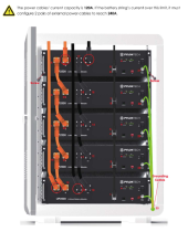
It is commono for an inverter or parallel inverters to require 400A or higher to operate or to accomodate serges. For example, a pair of 6548's together will output 13,000W, and to do so will require input from the batteries of 13,000/51.2 = 254A if the battery voltage sags, and we add for typical losses in the system this amperage draw increases. If we start up a large motor, that 13,000 W may go considerably higher for a few seconds.
Really there is only one proper way to handle the battery Energy Storage System:
Each battery to be properly protected needs to feed through a means of disconnect and a Class-T fuse to a main bus bar. One Bus for POS one Bus for NEG.
A set up with one, two, five, ten batteries doesn't matter, since each battery is independent of the others, each battery connects to these two bus bars.
Each battery can be safely connected or removed without touching the others, and each is separately protected in case of a short, without attracting current from the others. Size these main bus bars to carry the total max amperage of all inverters x 1.25 or more.
From each main bus, feed each inverter again with Class-T fuses between and 2P disconnects.
Each battery cable can each be sized to just the load of a single battery x 1.25 and you don't actually need to concern yourself about how many batteries may one day be in the system since it doesn't matter.
Following this approach, the system as a whole is safe, efficient and easy to work on/service.
To remove a battery, turn off the Pos disconnect between that battery and the bus, turn off the breaker on the battery itself, now there is no voltage on the cable connecting the battery and you can safely remove the cables. The rest of the batteries can safely remain in service, the inverters can remain in use, you can trouble shoot a single battery or swap it out and put another one in it's place, and you don't have to sit in the dark doing it because the balance of your system is still running.
Those radlock connectors can be sourced with a ring terminal end - or you can just modify one end of a cable. Use the radlock end to connect your battery and the ring terminal end can go to a 1P disconnect, then to a Class-T and then the bus.


