diy solar

diy solar

Question about autotransformer setup with quattro

Sal23

New Member
Joined
Apr 24, 2024
Messages
7
Location
USA
I am cross-posting it from victron energy forum. Will appreciate help with it. Details below:

Let us say we have ac coupled PV grid-tie setup with Quattro/Multiplus (i.e. grid backup) - to keep it simple, only AC out1 in Quattro outputs is in use. In such setup, the PV output is also routed to AC Out 1 port of Quattro/Multiplus. Now, if we add Victron autotransformer for load balancing, its input will be connected to same AC Out 1 port of Quattro. Autotransformer output is connected to main panel. That is, Quattro output will be balanced through it.

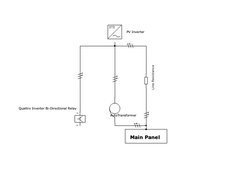
So, when the autotransformer (aka AT) is also connected, it seems to me that it now forms a parallel circuit to PV connection to Main Panel. So, any PV output that is going to main panel will now be routed through both existing PV lines and via autotransformer lines (with current split inversely proportional to resistance of each line). The same should be the case when Quattro is producing power - it will use both PV and AT connections to main panel.

I am including a single line diagram below outlining the above. Please note that in the diagram Quattro acts like either a sink or source (bi-directional relay).

The question is if my understanding above is correct. If it is correct, then it seems to me that autotransformer will indeed be in use all the time the power is produced by either PV or Quattro, not only when Quattro is inverting during off-grid. In case I have got anything wrong here, please correct me about what I got wrong here in the analysis of power flow.
 

Attachments

  • ac_coupled_pv_at_single_line_diagram.png
    ac_coupled_pv_at_single_line_diagram.png
    16.7 KB · Views: 6
That schematic looks funny.
I don't think auto-transformer is supposed to bypass inverter and make second path to grid.
I think its centertap neutral gets isolated when grid provides power relative to neutral, so L1/L2 just see it as an inductor. Then when grid is disconnected, it's center tap does get used.

But that's just from memory.

You should sketch out all lines L1/N/L2/G through each of the components, and include relays inside inverter and inside auto-transformer.
Your mention of neutral power will make sense to me (from the basics I know). Then my schematic is invalid because it assumes only line resistance, not induction. I will think about it some more. I do have the schematics (including relays inside - as documented by Victron) as well but perhaps there is no need for it at the moment because if the nduction part is correct, we are good.

Much appreciate your pointers.
 
Victron seemed to get this right, unlike some other brands which offered an auto-transformer to slap on a European 220V inverter and use on US 120/240V split-phase grid. Those designs, we kept finding ways to electrocute the hapless user, overheat the transformer, or over-voltage the loads.

I did feel like I would want to rewire Victron's use of the relay, however. The circuit didn't quite match what I thought was ideal.

Do you already have the Victron one? Both 32A and 100A models are limited to 28A continuous imbalance on neutral. If exceeded long enough to get hot, it will shut off all loads.

For a larger system (and fixed, not mobile), I might repurpose a used 25kVA transformer so any amount of imbalance would work.
 
I have ordered Victron 100A AT but not in hand yet. I am doing this for my sister's grid-tie solar setup. From what I know, there is not much load imbalance - the house consumes max 20Kw or so as power (mostly 240v appliances), but like 35Kwh average daily energy usage over the year (with peak usage of ~70Kwh in summer). So, at any instance, sustaining the imbalance is very unlikely to hit the max rating. Specs mention 32A for half an hour, 28A continuous on neutral like you mentioned. I am planning to connect it to Quattro 15KVA 230V inverter.

I am curious what would you like to rewire about the relay, and why. Any knowledge sharing is much appreciated.

Also, if you have any reading recommendation to understand autotransformer inductance, that will be appreciated. What I will like to understand how the neutral tap, induction, grid and relay work.
 
Imbalance meaning larger 120V load on L1 than on L2, or vice versa.
Two 15A 1800W loads on one side would be too much.

Note also the voltages aren't symmetric; Victron reused a 220V isolation transformer, with secondary voltage a few percent higher. Don't think that causes any trouble.

I'd have to look at their schematic again. One of them showed what's inside. The relay was either neutral passed through vs. to center-tap, or ground bond, and I wanted to do the opposite. I think.

Can one double up say the 100A autotransformer on a 15kVA 230V?

So long as you don't connect the imbalanced windings backwards ;)

But I'd repurpose the 2x 240V primary windings of a larger utility transformer, assuming I found one locally for a few $hundred.
 
I think this shows relay bonds neutral to ground, which is what's done for mobile application.


What I would feel like doing, for a stationary application, is keep neutral of output always hard-wired to neutral of grid, and it gets the bond from there.

I would repurpose the relay to connect center-tap of transformer to neutral when off-grid.

Their design attempts to derive neutral when on-grid, and it is not bonded to ground. So neutral runs at a skewed voltage due to transformer winding differences. I think neutral not bonded to ground violates US NEC.

1713994513246.png
 
I would repurpose the relay to connect center-tap of transformer to neutral when off-grid.

But then I have to worry about lost neutral, if it fails to close relay. That can over-voltage a load.
 
But then I have to worry about lost neutral, if it fails to close relay. That can over-voltage a load.
Thanks for explaining your take on the relay. Yep, a neutral bonded to ground for stationary application will be much simpler than a ground relay (perhaps a DIP switch or some kind of user override via a screw) - I had similar thought about this over-complication of natural and ground relay setup.

Perhaps we don't need a relay at all then? What could go wrong if the neutral is connected to grid permanently? This would be much simpler setup if possible.
 
Permanently connected, the 3% or whatever imbalance built into Victron auto-transformer would try to imbalance the grid.

One of the Youtubers showed a GroWatt auto-transformer drawing excessive current trying to rebalance the grid.

It may or may not be OK for you, depending on your grid imbalance, wire resistance, transformer characteristics.
 
Back
Top