fablau
New Member
- Joined
- Sep 21, 2022
- Messages
- 3
Hello everyone, I am a newbie here.
Although I am a software engineer and have a strong knowledge of electrical systems and electronics, I am NOT an expert in solar installations, hence my questions here and my need for help.
I'd need to replace an old Aurora Power One 3600w inverter for my 3kW home PV grid-tied system, which has burned out after over 10 years of service, and I find myself unable to easily replace it with any of the new inverters available nowadays on the market. My main problem is that most of the new inverters seem to not clearly explain how to ground both the grid and the PV side and have different characteristics and requirements from the old ones. I'll try to explain exactly what I am talking about here with pictures and data (below).
Here is a picture of how my system was previously hooked to the old inverter:

As you can see, both the output to the grid on the right and the PV input on the left are grounded (green cable).
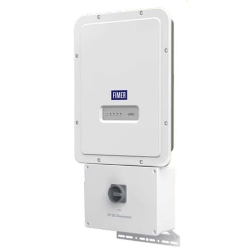
Now, I am thinking of replacing that old inverter with a new one by Fimer, with similar characteristics:
 www.invertersupply.com
You can find the installation manual at the link below:
And if you look through the manual, there is no picture showing how to connect the ground to the inverter. Furthermore, if you look at page 44 under the "Photovoltaic panel ground fault" section, you'll read the following:
This inverter must be used with photovoltaic modules connected with “floating” connections - that is, with positive and negative terminals that are not grounded. An advanced ground fault protection circuit continuously monitors the ground connection and disconnects the inverter when a ground fault is detected. The ground fault condition is indicated by a red LED on the front panel.
Does that mean that the ground MUST not be connected to the inverter? And if so, where do I need to connect it? And what about the ground from the grid side? It's very confusing to me, and I am stuck with this main problem to solve.
Another question I have is about choosing between "Independent channel configuration" and "Parallel channel configuration" (see page 62 of the same manual above). I don't know which one to choose because it looks like my old inverter didn't have that option! But from how it was hooked up, I guess it was in an "independent channel configuration" since I haven't noticed any "jumpers" in the old inverter and (as you can see from the picture above) the 4 wires coming from the PV system seem to be independent. Is there a proven way to understand that? What advice would you have for me on this?
And the last question for you guys is this: If you look at page 68 of the same manual, you'll see they talk about a "Rapid Shutdown" connection. It looks like that's something else I need to install, and I am wondering why I didn't have that in my previous inverter. Or was that already inside the inverter? Or is that already inside the fuse box I have for my home? Quite confusing to me...
Any thoughts and suggestions are very welcome!
Thanks in advance to anyone.
All the best,
Fab.
Although I am a software engineer and have a strong knowledge of electrical systems and electronics, I am NOT an expert in solar installations, hence my questions here and my need for help.
I'd need to replace an old Aurora Power One 3600w inverter for my 3kW home PV grid-tied system, which has burned out after over 10 years of service, and I find myself unable to easily replace it with any of the new inverters available nowadays on the market. My main problem is that most of the new inverters seem to not clearly explain how to ground both the grid and the PV side and have different characteristics and requirements from the old ones. I'll try to explain exactly what I am talking about here with pictures and data (below).
Here is a picture of how my system was previously hooked to the old inverter:
As you can see, both the output to the grid on the right and the PV input on the left are grounded (green cable).
Now, I am thinking of replacing that old inverter with a new one by Fimer, with similar characteristics:
Fimer UNO-DM-3.8-TL-PLUS-US-SB-RA-Q - Inverter Supply
Shop for Fimer UNO-DM-3.8-TL-PLUS-US-SB-RA-Q at Inverter Supply for best prices online. Fimer UNO-DM-3.8-TL-PLUS-US-SB-RA-Q, Fimer, UNO-DM-3.8-TL-PLUS-US-SB-RA-Q, Single-phase string inverter 3800Wac 2 MPPT, Fimer Inverters
You can find the installation manual at the link below:
And if you look through the manual, there is no picture showing how to connect the ground to the inverter. Furthermore, if you look at page 44 under the "Photovoltaic panel ground fault" section, you'll read the following:
This inverter must be used with photovoltaic modules connected with “floating” connections - that is, with positive and negative terminals that are not grounded. An advanced ground fault protection circuit continuously monitors the ground connection and disconnects the inverter when a ground fault is detected. The ground fault condition is indicated by a red LED on the front panel.
Does that mean that the ground MUST not be connected to the inverter? And if so, where do I need to connect it? And what about the ground from the grid side? It's very confusing to me, and I am stuck with this main problem to solve.
Another question I have is about choosing between "Independent channel configuration" and "Parallel channel configuration" (see page 62 of the same manual above). I don't know which one to choose because it looks like my old inverter didn't have that option! But from how it was hooked up, I guess it was in an "independent channel configuration" since I haven't noticed any "jumpers" in the old inverter and (as you can see from the picture above) the 4 wires coming from the PV system seem to be independent. Is there a proven way to understand that? What advice would you have for me on this?
And the last question for you guys is this: If you look at page 68 of the same manual, you'll see they talk about a "Rapid Shutdown" connection. It looks like that's something else I need to install, and I am wondering why I didn't have that in my previous inverter. Or was that already inside the inverter? Or is that already inside the fuse box I have for my home? Quite confusing to me...
Any thoughts and suggestions are very welcome!
Thanks in advance to anyone.
All the best,
Fab.
 ), they need an conveniently-located, ground-level accessible, manual switch, which can remotely disconnect the power as close to the power source (the solar panels) as possible.