diy solar

diy solar

Repurposing an A123 Prius brick (616x 26650A cells)

brewmium

What r u new? Yea.
Joined
Feb 3, 2020
Messages
43
Hi all,

So, I have a used one of these:

Photo


The sticker on the outside says it's a 188v, 25Amp hour system, and my goal is to turn it into my 24v backup battery system.

The thing has been sitting for... well... I've owned it for 5 years, and i think it was pulled out of service a few years before that. So, 7 years? It was a state Prius, so it really didn't stay in service very long. :)

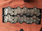
After cracking it open, and carefully extracting one of the 14 subsystems, it turns out they are 12 volt blocks. :)

I was surprised to find the sub-system actually reading 12.69 volts on my meter.

The 14 containing subsystems have 4x11 26650A cell banks in series (guess that's obvious from the pics... and the 12 volts.)
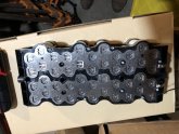
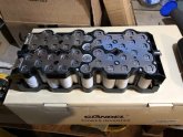
IMG_0654.JPG IMG_0652.JPG

I'm very happy i don't have to tear them apart to create the 24v groups i eventually need.

While removing the subsystem, I carefully extracted the PCB from the end (each one manages 2 of these bricks). I know NOTHING about the BMS or charging systems built into the rest of the thing, so I'm thinking I just take the 14 subsystems to create a 7x2 24v battery with my own everything else.

While I am super old to the whole EE thing, i am super know nothing about current battery tech, let the learning begin. :)

I am going to do a ton of current tech learning, but if anyone wants to chime on with a "what next" I would be very grateful!

best,
-eric
 
So, sounds like in battery speak, that subsystem is a 4s11p, or is that 11p4s? I'm really concerned that balancing will be an issue, as they are already assymbled. :)
 
Wait... are these LFP or Lion?

I too am a bit confused... guess that's obvious. :)

Hope i didn't post in the wrong section! I see there is a second life section now, sorry for being so new. :oops:
Is it possible to move? or should I repost?

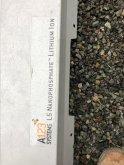
They are A123 cells, in one of their boxes from... '07?

Here's the outer case, their choice of wording made me think wrong, maybe?
IMG_0655.JPG


and one of the cells i can get good numbers from
IMG_0658.JPG

Thanks a bunch for responding!
-eric
 
Last edited:
Those cells fully charged should be 16.8 Volts per bank... at 12.8, they are quite discharged.
 
Nope, they should be LiFePO4 so 12.8 would be full... A123 nanophosphate SHOULD be right... I wish more info was on them.
 
Since the pack has full voltage marked on it, totaling up the S-count should get us a cell voltage... time to count it up.
 
The stock photo shows 14 banks per pack, divided into 188 is 13.43v... divided by 4 is 3.36V, so... LFP...
 
So, for a 24v system, I would get a BMS on the 7 pairs of banks?

Yeah, you'd probably want an 8s BMS on each set of two in series. It may be able to be configured in a better way, but it's tough to say without a close look, and/or a lot of work. ex: Reconfiguring each pack into large 3.6v packs might be pretty easy, 8 of those in series for 24v and you'd only need one BMS. But you'd be short a pack to make a 2p setup if my math is right...
 
Last edited:
Thank you very much for the charging sheet info! Knowing where to even look is one of the many places where I don't even know where to start.

ex: Reconfiguring each pack into large 3.6v packs might be pretty easy, 8 of those in series for 24v and you'd only need one BMS. But you'd be short a pack to make a 2p setup if my math is right...

Eeek!!! I hope you aren't suggesting tearing the 14 packs apart into individual cells??

I think i need to do some more research so I can ask more "intelligent" questions. :)
 
Eeek!!! I hope you aren't suggesting tearing the 14 packs apart into individual cells??

No, just turning each 11p4s 12.6v pack into a 44p 3.6v pack by removing a few series busbars and adding parallel busbars (nickel strips). Then you hook 8 of those in series (you'd have 6 left over) . Or parallel two and put 8 of those in series (you'd be short two packs).

My explanation sounds confusing...sorry!
 
No, just turning each 11p4s 12.6v pack into a 44p 3.6v pack

Oh, now that makes a ton of sense. I was thinking of things the wrong way. The back of all 44 are on the same nickel sheet, so it's just fiddling with the top. TYVM! :)
 
The Prius had NiMH batteries up until 2015, when they made the switch to Li-ion, so these may not be too old.

This is actually an after market brick that goes in place of the spare, made by A123 in '07 (ish)
 
Last edited:
Oh, now that makes a ton of sense. I was thinking of things the wrong way. The back of all 44 are on the same nickel sheet, so it's just fiddling with the top. TYVM! :)
Methinks you will need to cut the sheets on both sides to parallel up the cells.
 
Yep, i've got the spots drawn. What i was grinding over last night was other options. Unfortunatly, the plastic housing was put on before the spot welds, so seperating them into 4 descrete parallel components is probably the wrong direction. As you can see from the pics, they are a chris/cross pattern, I'm going to have a fair bit of chris/cross wire/nickel making up for that. I was thinking, if i brought multiple fo these things into the mix, i could make shorter connections.. but that sounds less flexible in the long run.

img_0665-jpg.6809
IMG_0660.JPG
If you can make it out, i've marked the +/- parts, and cut lines.

Screen Shot 2020-02-06 at 9.36.33 AM.png
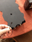
Also, there is this connector coming out, and (circled) a wire that comes from the back of the pack, up to wrap around one of the lugs that the controller PCB bolts to. I'm wondering if one of these are a temp sensor, and???

I don't own a spot welder, and the China Supermarket may not be so available (and they seem to ALL be junk, and the DIY setups are way out on delivery). I really don't want to spend more than i have to on a spot welder. I'm thinking I may get a heat sink on the nickel plate, and with a good pre-tin i shouldn't create too much heat. I used to solder ICs on/off of mainframe motherboards... only 35 years ago... I'm sure it will come back. ;)

What fancy new tech are you all using as a flat insulator these days? The sticky board that protects the nickel sheets on these is awesome stuff, I've had it on and off a few dozen times and it's still happily sticky to go back on. I'm wondering if I can find some more of that! I will end up with a multi-layor chris/cross of "bus bar" in the middle of those 4 parts.

thanks all!
 

Attachments

  • IMG_0665.JPG
    IMG_0665.JPG
    116 KB · Views: 84
For a decent spot welder, you can get a starter solenoid, a contact switch, and some copper nails. Hook it all up, and tie it to a big battery, and with a little practice you can make decent spot welds.
 
For a decent spot welder, you can get a starter solenoid, a contact switch, and some copper nails. Hook it all up, and tie it to a big battery, and with a little practice you can make decent spot welds.

I think i saw someone on youtube with that kind of setup. thanks!
 
One of the 4 subsystems is a bit out of voltage from the other 3 (3.2, 3.2, 3.19, and 3.16), do i need to get them all to the same charge before paralleling them up?

Oh, and i found some LPDE flat sheet that should work for insulating my nickel chris/cross strips. I'll post the results of that.
 
One of the 4 subsystems is a bit out of voltage from the other 3 (3.2, 3.2, 3.19, and 3.16), do i need to get them all to the same charge before paralleling them up?

From my experience that is plenty close enough. Soldering nickel strips to nickel strips should be pretty easy. I'd use a big enough iron with chisel tip so it goes quickly without heating up the cells. I've seen the starter solenoid DIY spot welders and they will work, but the battery size and discharge properties is a huge factor on if the welds are too hot or too cold. I've seen people say a 40ah LA battery is somewhere around the sweet spot, but who knows? If you had to do all the cells separately, a spot welder would be the way to go, but since you already have the nickel strips to solder to...I myself would try that route first.

I have no experience with LPDE, but sounds good. I've been using Kapton tape for a lot of battery projects lately. It's very thin, so not always good by itself, but the high heat resistance and lack of adhesive transfer when removed makes it great for many things.

Since you don't have the exact # of those packs you'll need for your 24v setup, I was thinking of maybe tying those packs together with the nickel busbars... Like 3 of those packs together would make 2 individual 3.2v batteries. All cells facing one way will be one 3.2v battery, and all facing the other way would be another...which may make for less criss-crossing? That way you'd use 12 out of your 14 packs, and have two left for spares. It's tough to give advice like that without seeing and handling them up close, but it seems like you have the knowledge to clearly handle that on your own.

Don't cut anything until you are 100% sure...as those packs look pretty handy for other projects as-is. It's a tough thing to do, modify an already good 12v pack!
 
Last edited:

diy solar

diy solar
Back
Top