South Haven Solar
New Member
I'm a tinkerer, so I've designed a house with both a dc and ac coupled system in mind. I've completed the dc-coupled system, it is a XW Pro and dual MPPT setup of 13 panels on the east/west roofs (limited roof space).
I'm now looking to the smaller south-facing hip roof to squeeze an additional 4 panels in. I would like it to be AC coupled because I am lucky enough to have a net metering arrangement. The DC coupled setup isn't sized to export or store any more power during peak hours.
I'm stuck with the 4 panels I purchased, but the inverter for the ac coupled setup can be anything. There are 3 facets on the south roof, so I had microinverters in mind. Upon researching them, I found that even the IQ8H-240 reccomends use with traditional 72 cell or 144 half-cell modules and a max input of 60 VDC. I have Q.Peak Duo XL-G10.3 / BFG panels with a Voc of potentially >60 VDC under the right circumstances. I have read sad posts documenting fried microinverters because of this kind of mismatch.
You may be asking yourself why I purchased 156 half cell panels with a potential for a Voc that exceeds reccommended microinverter specs. It's because I messed up! The 4 panel south roof project was an afterthought at the time I was purchasing panels.
I've considered several solutions, including:
A) A 200 W 1 ohm resistor with aluminum heat sink in series with each microinverter and panel. Fire hazard.
B) Simply waiting until Enphase launches the IQ9 product line.
C) A string inverter, even though the roof has three facets.
D) Buying smaller panels. Then I don't have this interesting problem anymore.
E) Buying 4 Enphase IQ8M and hoping for the best.
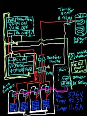
F) A solution that is off the rails and the reason I'm asking the DIY community for help. I've considered wiring a water heater element in parallel to the microinverters with enough load to prevent the working mppt voltage from approaching 45 V. The AP system DS3 and the Enphase IQ8M both have a max mppt voltage range of 45 V. My panels have a Vmpp of 45.3 V, Impp 11.6 A.
If you're wondering how I would implement this, I've posted a sketch showing voltage sensing controllers, SSRs, and diodes. The run from the roof to the panel and equipment is about 25 ft. The run to the water heater would be about 50 ft. I'm considering a constant 3.6 ohm resistor (two 120 V 2000 W elements in parallel).
This lead to a number of considerations for which I'm seeking the community's insight:
1) Would a 100-200 watt resistive load per panel mean the mppt is unlikely to operate above 45 V under load?
2) Is a fixed parallel resistor going to completely confuse the micros? In theory, a series resistor wouldn't confuse them, but I encountered problems with that solution.
3) Looking at an IV curve, it seems like the only reliable way to keep the voltage under load below Vmpp is to ensure the current under load exceeds Impp. The only way to ensure that is to put in a resistive load (heating element) of ≤ or ~1 ohm ensuring that the heater current exceeds Impp. Which means I might not be getting much AC power out of my microinverters. Is this understanding correct? Can I count on a lower voltage under load in lower insolation conditions?
4) Is this a good application for blocking diodes? From what I've read here, their use in parallel panel strings is discouraged, but maybe this is a good application? I need some kind of protection from panels feeding the other micros. Perhaps I need multi-loop elements and individual runs so there is no chance a micro ends up in parallel with multiple panels?
5) How worried should I be about the Voc climbing when the grid goes down? My thought is that microinverter damage would be incurred from exposure to high input voltage over a long period of time; not necessarily from a temporary event.
6) Safety of the water heater. This is a dump load to protect the microinverters, but I'll gladly sacrifice the micros in a fail state to prevent a household danger.
Lastly, I should mention code. My inspectors are working off an older residential code, but I have tried to work within the 2020 NEC and have fulfilled 690.12 requirements for the other roof arrays. But I didn't have to in my jurisdiction. I realize my water heating solution probably creates code violations that I haven't even thought of.
I'm now looking to the smaller south-facing hip roof to squeeze an additional 4 panels in. I would like it to be AC coupled because I am lucky enough to have a net metering arrangement. The DC coupled setup isn't sized to export or store any more power during peak hours.
I'm stuck with the 4 panels I purchased, but the inverter for the ac coupled setup can be anything. There are 3 facets on the south roof, so I had microinverters in mind. Upon researching them, I found that even the IQ8H-240 reccomends use with traditional 72 cell or 144 half-cell modules and a max input of 60 VDC. I have Q.Peak Duo XL-G10.3 / BFG panels with a Voc of potentially >60 VDC under the right circumstances. I have read sad posts documenting fried microinverters because of this kind of mismatch.
You may be asking yourself why I purchased 156 half cell panels with a potential for a Voc that exceeds reccommended microinverter specs. It's because I messed up! The 4 panel south roof project was an afterthought at the time I was purchasing panels.
I've considered several solutions, including:
A) A 200 W 1 ohm resistor with aluminum heat sink in series with each microinverter and panel. Fire hazard.
B) Simply waiting until Enphase launches the IQ9 product line.
C) A string inverter, even though the roof has three facets.
D) Buying smaller panels. Then I don't have this interesting problem anymore.
E) Buying 4 Enphase IQ8M and hoping for the best.
F) A solution that is off the rails and the reason I'm asking the DIY community for help. I've considered wiring a water heater element in parallel to the microinverters with enough load to prevent the working mppt voltage from approaching 45 V. The AP system DS3 and the Enphase IQ8M both have a max mppt voltage range of 45 V. My panels have a Vmpp of 45.3 V, Impp 11.6 A.
If you're wondering how I would implement this, I've posted a sketch showing voltage sensing controllers, SSRs, and diodes. The run from the roof to the panel and equipment is about 25 ft. The run to the water heater would be about 50 ft. I'm considering a constant 3.6 ohm resistor (two 120 V 2000 W elements in parallel).
This lead to a number of considerations for which I'm seeking the community's insight:
1) Would a 100-200 watt resistive load per panel mean the mppt is unlikely to operate above 45 V under load?
2) Is a fixed parallel resistor going to completely confuse the micros? In theory, a series resistor wouldn't confuse them, but I encountered problems with that solution.
3) Looking at an IV curve, it seems like the only reliable way to keep the voltage under load below Vmpp is to ensure the current under load exceeds Impp. The only way to ensure that is to put in a resistive load (heating element) of ≤ or ~1 ohm ensuring that the heater current exceeds Impp. Which means I might not be getting much AC power out of my microinverters. Is this understanding correct? Can I count on a lower voltage under load in lower insolation conditions?
4) Is this a good application for blocking diodes? From what I've read here, their use in parallel panel strings is discouraged, but maybe this is a good application? I need some kind of protection from panels feeding the other micros. Perhaps I need multi-loop elements and individual runs so there is no chance a micro ends up in parallel with multiple panels?
5) How worried should I be about the Voc climbing when the grid goes down? My thought is that microinverter damage would be incurred from exposure to high input voltage over a long period of time; not necessarily from a temporary event.
6) Safety of the water heater. This is a dump load to protect the microinverters, but I'll gladly sacrifice the micros in a fail state to prevent a household danger.
Lastly, I should mention code. My inspectors are working off an older residential code, but I have tried to work within the 2020 NEC and have fulfilled 690.12 requirements for the other roof arrays. But I didn't have to in my jurisdiction. I realize my water heating solution probably creates code violations that I haven't even thought of.