diy solar

diy solar

RS-485 and CAN "features" with 2x interconnected Seplos v16 BMS and CerboGX

Mariner62

New Member
Joined
Dec 29, 2020
Messages
84
Hi Seplos Gurus,
I have two Seplos Mason 280 systems where the V16 BMS are interconnected with RS-485 and also connected to a Victron CerboGX via CANbus. Pack0 is connected to the CerboGX via CAN, Pack1 is connected to Pack0 via RS485.

I have noticed some interesting behaviour, which I would like to better understand if this is just a limitation, or whether its something I can fix.

When I set the DIPs as follows, then I get the behaviour below:
Pack 0: ALL OFF, Pack 1: DIP1 ON, rest are OFF.

1. The CerboGX detects a Pack0 only.
2. When I connect my PC via RS485 (running the Seplos host software) to Pack0, I can access both Pack0 and Pack1 from the software and everything works fine.

This is ok except, the CerboGX only thinks I have one pack with 280Ah capacity. I need it to recognise both packs.

So, following the SEPLOS manual, I set the DIPS as follows, to get the CerboGX to recognise both packs:
Pack 0: DIP5 is ON, rest are OFF, Pack 1: DIP1 ON, rest are OFF.

3. The CerboGX now detects both packs and correctly reports 560Ah capacity.
4. When I connect my PC via RS485 (running the Seplos host software) to either Pack then the 485 comms don't work and I cannot access anything.

Interestingly, if I switch the Pack0 DIP5 from OFF to ON while PC is connected and accessing the system (from either pack) then the comms continue, but I cant switch packs, and if I break the coms and re-connect then it doesn't work any more.

I would like to get a configuration working which allows me to access both packs from the PC and also have the CerboGx recognise both packs (ie Pack0 DIP5 needs to be ON).

Unfortunately I have not found a way to do this ... any clues anyone??

Cheers all
 
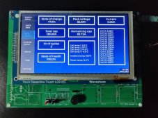
This is a known issue of Seplos BMSes. See recent videos covering Seplos from Off Grid Garage YT channel. I decided to solve this issue by building custom device which will be connected in between Seplos BMSes (all in slave mode) and an inverter. It will collect data from individual BMS via common RS485 bus and provide consolidated info to the inverter. It will also allow to specify charge/discharge voltage and current limits and provide them to the inverter. This will allow charge voltage to be set to different than total overvoltage protection voltage set on the BMS. It is in early development process, but it can get data from Seplos BMSes in slave mode (see picture). Right now I am working on emulation of "master" BMS against Axpert King set in "PYL" mode using a separate RS485 bus. Integration of CAN communication with inverters will follow later. BMSes from different brands may be integrated as well. The plan is to apply this solution to 16 x 16s 138Ah packs connected in parallel, each pack with its own Seplos BMS.

Basic specification of the device:
  • Integrated 48VDC DC-DC converter (device is powered by battery pack voltage)
  • 4x RS485/RS232 interfaces (connection of BMSes, inverters, smart meters or other BMS master devices)
  • 2x CANBUS interface (connection with inverters)
  • 8x digital input (e.g. control switches, storage system enclosure tamper switches, DC contactor state switches, etc.)
  • 4x analog inputs (e.g. auxiliary thermistors)
  • 4x 5V output (e.g. auxiliary LED indicators)
  • 2x relay output (e.g. for generator control)
  • 2x bi-stable relay output (for main DC contactors)
  • 2x 48VDC FAN output with PWM speed control and RPM monitoring (forced cooling if required)
  • Ethernet interface (connectivity to backend cloud services and IoT platforms)
  • Wifi interface (connectivity to backend cloud services and IoT platforms)
  • Bluetooth LE interface (future smartphone apps possible)
  • miniPCIe slot (optional cellular modem -2G/4G, NB-IoT, LTE-M)
  • 7” 800x480 touchscreen
  • 10x RGB LEDs (SoC and alarm state indication)
  • 2x backlit panel switches (START/STOP – emergency galvanic disconnect from the load using DC contactors)
  • USB (type A connector) for connection of mass storage devices (long term logs, etc.)
 

Attachments

  • BMS monitor screen.jpg
    BMS monitor screen.jpg
    656.1 KB · Views: 53
This is a known issue of Seplos BMSes. See recent videos covering Seplos from Off Grid Garage YT channel.
Not quite ... as I understand it Andy had different sized packs and different Revs of BMS, so it was guaranteed not to work from the start. (Entertaining to watch though!). I have identical packs and the latest identical BMS build.

I like your thinking on building an external gizmo, but it shouldn't be needed if SEPLOS fix up their software.

I don't need to access the Battery Monitor interface very often, but I like to keep an eye on cell balance at certain times. The simple solution is to flick DIP 5 OFF for a short time and have a look at what I want to see, then flick it back to the ON setting.
 
Not quite ... as I understand it Andy had different sized packs and different Revs of BMS, so it was guaranteed not to work from the start. (Entertaining to watch though!). I have identical packs and the latest identical BMS build.
I asked Seplos support if a BMS becomes unavailable to Battery Monitor app when it is switched to master mode and they confirmed it. It is actually logical, because when you switch DIP5, it will become a master BMS that means that it will stop responding to requests from other masters, including the app. When all DIPs are off, it is a slave with address 0.
 
This is a known issue of Seplos BMSes. See recent videos covering Seplos from Off Grid Garage YT channel. I decided to solve this issue by building custom device which will be connected in between Seplos BMSes (all in slave mode) and an inverter. It will collect data from individual BMS via common RS485 bus and provide consolidated info to the inverter. It will also allow to specify charge/discharge voltage and current limits and provide them to the inverter. This will allow charge voltage to be set to different than total overvoltage protection voltage set on the BMS. It is in early development process, but it can get data from Seplos BMSes in slave mode (see picture). Right now I am working on emulation of "master" BMS against Axpert King set in "PYL" mode using a separate RS485 bus. Integration of CAN communication with inverters will follow later. BMSes from different brands may be integrated as well. The plan is to apply this solution to 16 x 16s 138Ah packs connected in parallel, each pack with its own Seplos BMS.

Basic specification of the device:
  • Integrated 48VDC DC-DC converter (device is powered by battery pack voltage)
  • 4x RS485/RS232 interfaces (connection of BMSes, inverters, smart meters or other BMS master devices)
  • 2x CANBUS interface (connection with inverters)
  • 8x digital input (e.g. control switches, storage system enclosure tamper switches, DC contactor state switches, etc.)
  • 4x analog inputs (e.g. auxiliary thermistors)
  • 4x 5V output (e.g. auxiliary LED indicators)
  • 2x relay output (e.g. for generator control)
  • 2x bi-stable relay output (for main DC contactors)
  • 2x 48VDC FAN output with PWM speed control and RPM monitoring (forced cooling if required)
  • Ethernet interface (connectivity to backend cloud services and IoT platforms)
  • Wifi interface (connectivity to backend cloud services and IoT platforms)
  • Bluetooth LE interface (future smartphone apps possible)
  • miniPCIe slot (optional cellular modem -2G/4G, NB-IoT, LTE-M)
  • 7” 800x480 touchscreen
  • 10x RGB LEDs (SoC and alarm state indication)
  • 2x backlit panel switches (START/STOP – emergency galvanic disconnect from the load using DC contactors)
  • USB (type A connector) for connection of mass storage devices (long term logs, etc.)
Hello,

Is it possible to have informations about your custom device ?
 
Hello, for now we will use the device only as a part of complete ESS. We are currently not planning to offer the device as stand alone.
bummer, Also ran into problem cant use 3 seplos packs with rs485 and CAN to CerboGX
 
So in layman's terms do I understand the following?
If the master battery is left in normal mode (sw5 off) the whole stack will run RS485 comms and this will allow you to monitor either with solar assistant and/or push RS 485 battery data to the inverter.
If the master battery is put into CAN mode (sw5 on) then you can only monitor the second and subsequent batteries with RS485 for solar assistant but the master battery will interrogate all the batteries and collect the data and push it to the inverter via CAN.
 
@Quattrohead thats almost correct, however you can split – either with a splitter or a self made cable – the master CAN Port on the BMS and read the master via RS485 (baud 9600) while keeping the CAN communication between the master and the inverter and reading the second and subsequent packs with a separate RS485 (baud 19200) connection through either one of the masters RS485 ports or one of the last packs free RS485 port.
 
Great, so CAN and RS485 at 9600baud are both always active on the port, just got to split the cable. Cool.
Then packs 2 through x can be read vis RS485 at 19200 baud.
Also the master battery can collate packs to through x data but not adding its own data on that RS485 link, correct ?
What a palava.
 
Back
Top