So I'm hoping to move my batteries in my RV to a more central location approximately 20 feet from the converter. When calculating wire size, do I go off the max output of the converter (55 amps) or the max that the battery can feed back to the power distribution on the same wire? Going with 3 12v 100ah lifepo4, so up to 300 amps max discharge but I don't think anything other than an inverter would pull that. In that scenario, I assume I would put the inverter extremely close and use 300 amps to calculate.


You are using an out of date browser. It may not display this or other websites correctly.
You should upgrade or use an alternative browser.
You should upgrade or use an alternative browser.
Rv Converter to Battery wire size
- Thread starter NotLost
- Start date
NVS
Solar Enthusiast
- Joined
- Sep 14, 2021
- Messages
- 373
I put bus bars in the original battery location, and connected all the current wiring to those bus bars. Then I used a heavy enough wire to carry load back to the bus bar. This way I wasn't trying to rerun all the wires that were connected the to the new battery.
Attachments
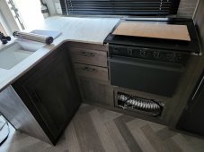
So, little bit more information. I haven't fully decided yet on how I'm going to wire it. Final location, the area in the kitchen in the corner between the sink and the stove. Initially, I'm thinking I would run from the factory installed battery disconnect on the front of the camper, it's about 6 feet over and 12 feet back from there to the battery bank. Using the charts for 60 amps (charger max) at 25 feet I get a 4 or a 2 if I remember correctly. This would be on top of the 25+ feet of #8 going from the converter to the front of the camper.
Now, if I run from the converter to the new location directly it's also about 25 feet. But then I would need to run a new disconnect, re-run solar, and figure out what to do at the converter to power the factory wiring which has power for the powered tongue jack at least.
Now, what about in between the batteries? 2/0 or 4/0, in preparation for the inverter? What size fuse, 125 for each battery or does it need to increase as I add batteries? 1st in parallel chain 125, 2nd 225+, 3rd 325 etc? But then just a say 65ish back to the converter?
Attachments
Last edited:
John Frum
Tell me your problems
- Joined
- Nov 30, 2019
- Messages
- 15,230
What is the maximum continuous load you are planning for?
If you are not sure its usually a good idea to at least plan for the max continuous draw from your inverter.
Will you be running and inverter or an inverter/charger?
As for the running gear and breakaway system...
Suggest you isolate them and otherwise leave them as is.
Let it be energized by the 7 way tow cable and leave the tongue battery in place to power the breakaway system.
Now you only have to integrate the new system with the legacy ac/dc distribution panel.
How far is the new system location from the legacy ac/dc distribution panel?
UPDATE: I see it is a 40 foot round trip to the legacy ac/dc distribution panel.
I suggest you look for some place much closer especially since you are appear to be doing a 12 volt system.
30 amp RV, 12 volt 300ah battery bank. The total length is why I would prefer to run back to the converter directly and cut my wire runs in half instead of using the factory location. I might be better off running a 4 back to the converter, and then a join the new and factory wire together there before attaching to the converter.
My 3rd option, which isn't space friendly but still possible, is right at the converter. It's a camper with a bunk house in the back, the converter is under one of the bunks. It's a 30 foot camper, so any waster space is basically in the middle, that's why it seems like it's 15-20 feet no matter where I go.
My 3rd option, which isn't space friendly but still possible, is right at the converter. It's a camper with a bunk house in the back, the converter is under one of the bunks. It's a 30 foot camper, so any waster space is basically in the middle, that's why it seems like it's 15-20 feet no matter where I go.
The 3x 100Ah home-built batteries (looking good, BTW) each have a BMS which is programmed for maximum continuous and maximum peak current values - or in the case of some brands such as JK, the maximum peak is a property of the BMS itself, and not separately configured. I SWAG the "peak output current" of your cells to be 200A, for a few seconds. The fuse on EACH battery pack should be fast-acting class-T and no larger than that figure - the fuse should be protecting both BMS and the cells within the pack from higher current (which should only be present in the case of a short-circuit disaster, in which case you WANT and NEED the corresponding fuses to blow very fast.)
Going to a shared bus, that theoretically calls for a wire size of 4/0 (from each pack). However, depending on your planned Inverter size (which you have not yet indicated for us!) you could maybe consider using 2/0 from each pack, wired with matching lengths to the "12v" and "grounding" bus bars.
Within my own RV, I actually use the Inverter DC input lugs as my main "bus bars" for parallel packs, with cables from each battery all joined together at those inverter lugs ("12-VDC main input power" and "12V Grounding" respectively). Those lugs (each) also have a 3rd cable, also large, going to a car-audio-type "power distribution blocks". Whether the Inverter is powered up or turned off, the Inverter's big power lugs provide a wonderful "bus bars" for "12v" and grounding among these cables at all times. In my case, those cables are very short, and only 2/0 AWG in size. They're sized for the total capability of the Inverter while supporting AC loads, PLUS the total of all the RV "12-VDC loads added together.
- - -
Depending on the model of "Converter" and likely integrated "12-VDC Distribution Fuse Board", you will probably want to change the DC wiring at that panel. For the common case of WFCO panels, they traditionally wire one "12V" supply wire into the fuse board from the Power Converter, and another from Battery Bank. On the fuse Boards of my vintage, both of those connector ports are limited by normal-sized automotive ATC fuses (not "medium" sized, not "maxi" sized). These fuses are not generally available in sizes larger than 50A. If your Power Converter/Charger can dish out 60A, previous lead-acid batteries might not have taken it all in - and most power converters spend nearly all of their time in "float mode" anyway, putting out relatively low voltage and current.
Depending on your MAKE AND MODEL of power converter, it might actually be willing to push up to 60A into hungry LiFEPO4 battery packs. Two issues could arise in that case: #1, the maximum charging current of each "100Ah" battery pack should be limited to only 50A, so you'll generally need multiple packs accepting charge current (if you can't program a "smart" power converter to behave in a genuinely "smart" way). #2, it will exceed the maximum capability of the "12-VDC Distribution Fuse Board" main port fuses. To bypass the second issue, you will want to add another small 3-way power distribution block between the power converter and the 12VDC fuse board:
- 1 wire is the "12V" output from the power converter;
- 2 wires may now connect to BOTH main input ports of the 12-VDC fuse board, providing a higher total of power input (perhaps around 60-70A) for the RV's DC appliances;
- one wire (BIGGER) goes back to the "12v bus" or power distribution block near the batteries and Inverter. (This wire supports 2-way current, both charging the batteries and pulling from the batteries from the case of running RV "12-VDC" appliances attached at the 12-VDC fuse board).
Are you making an energy audit, to size the Inverter? Please also advise of your make/model of DC 12v distribution (fWFCO or PD-integrated "DC fuse Board" board, or a separate 12v "panel" installation with fuses on board), and your power converter/ charger model.
Little bit more component info:
Biggest 120 volt load is going to be the microwave, a 900 watt unit that consumes 1.35kw so I'm planning on a 1500 watt inverter.
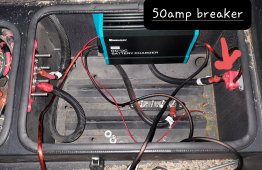
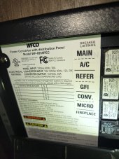
PDP is a WFCO WF-8955PEC. Pictures attached. I will be using a Progressive Dynamics WFCO Lithium Replacement for the WFCO-8955. PD4655LIV (55-AMPS)
First I'm trying to size the wire to get to the bank. Second, wire and fuse sizes to connect the batteries together. 3rd, size it big enough for the eventual install of an inverter.
Biggest 120 volt load is going to be the microwave, a 900 watt unit that consumes 1.35kw so I'm planning on a 1500 watt inverter.
PDP is a WFCO WF-8955PEC. Pictures attached. I will be using a Progressive Dynamics WFCO Lithium Replacement for the WFCO-8955. PD4655LIV (55-AMPS)
First I'm trying to size the wire to get to the bank. Second, wire and fuse sizes to connect the batteries together. 3rd, size it big enough for the eventual install of an inverter.
The "900 Watt" microwave is a 120-VAC device with extremely high reactance, you should not attempt to use an Inverter rated for less than 3000/6000 watts in running that appliance. "Reactance" means that it sort of "barfs-back" out-of-phase power loads to the power generator (grid or Inverter), rather than absorbing power in a manner which is compatible with the sine-wave voltage distribution of the "Hot" wire. A smaller Inverter will die young, if it can even run at all.Little bit more component info:
Biggest 120 volt load is going to be the microwave, a 900 watt unit that consumes 1.35kw so I'm planning on a 1500 watt inverter.
PDP is a WFCO WF-8955PEC. Pictures attached. I will be using a Progressive Dynamics WFCO Lithium Replacement for the WFCO-8955. PD4655LIV (55-AMPS)
First I'm trying to size the wire to get to the bank. Second, wire and fuse sizes to connect the batteries together. 3rd, size it big enough for the eventual install of an inverter.
I'm familiar with that WFCO, quite a bit a bit less familiar with the PD-4655LIV. PD changes the controlling ROM microcode of their power converters from time to time, without declaring the device to be a "new model". In its first versions, that PD power converter pushed 14.6V charging voltage into the "Lithium 12v" battery pack at all times, a terrible idea which hurt lifespan of the battery cells. It might be better at this time. I own a slightly modified PD called a "WildKat", and I have set the DIP switches for GEL/AGM instead of Lithium. When I have a reason to prefer fast charging, I use the charge wizard pendant to push it up to "boost" voltage. (If you needed to charge from a generator, rather than a plug-in, you would want to do that). The "LIV" model, IIRC, is Lithium ONLY, and does not provide DIP switches to set it operating in AGM/GEL mode. If you don't need fast charging via a generator, you could also consider a Victron: The 'Blue Smart IP67 Charger 12/25 120V NEMA 5-15' charger provides for less than half the power, but it's fully programmable and controllable via a cellphone/bluetooth App. It's so much more efficient that it dopesn't even need a fan, and it does fit in the lower WFCO compartment. I've got some customers buying that one instead, using this low-cost offer from BattleBorn: https://battlebornbatteries.com/product/victron-bluesmart-ip67-12-25-12v-25a-charger-nema-5-15/
Your photo wasn't attached, but I know the WFCO very well. In addition to my instructions from the lower half of post #10 (adding small DC distribution blocks behind the WFCO panel), you will need to buy another circuit breaker for the 120-VAC side, as follows:Little bit more component info:
Biggest 120 volt load is going to be the microwave, a 900 watt unit that consumes 1.35kw so I'm planning on a 1500 watt inverter.
PDP is a WFCO WF-8955PEC. Pictures attached. I will be using a Progressive Dynamics WFCO Lithium Replacement for the WFCO-8955. PD4655LIV (55-AMPS)
First I'm trying to size the wire to get to the bank. Second, wire and fuse sizes to connect the batteries together. 3rd, size it big enough for the eventual install of an inverter.
In typical RV WFCO wiring, a single '15A' breaker has been used in the upper left 120-VAC section, with a split output wire feeding BOTH the power converter and another downstream circuit (sometimes the initial GFCI for a set of outlets, sometimes some other things). Those should be be split onto separate breakers, so that you may conveniently TURN OFF THE CONVERTER/CHARGER when supplying power via the Inverter. (Without doing that, you will have a power-wasting loop: Inverter pulling from the batteries and discharging them, power converter/charger pulling 120-VAC from the Inverter to try and charge the batteries back up.) Buying a "dual" single-slot, single-bus breaker makes it possible to leave the outlets on while turning off power into the Converter. You can use either a 15/15 or a 15/20, if all the non-converter (outlets, GFCI, or whatever) was built using AWG-12 Romex or larger wires. (AWG-14 Romex must be limited to 15A tops). This one fits older models of the 120-VAC "30A" WFCO power center, and I don't think that they've changed in more recent versions of the power center. The 15/15 version costs considerably less: https://www.amazon.com/Siemens-Non-Current-Limiting-Circuit-Breaker/dp/B000WUL458/
Your behind-the-WFCO power distribution blocks can be bought as a pair, this item: https://www.amazon.com/VonSom-Distribution-Distributor-Connecting-Amplifier/dp/B08BLJFD5J/
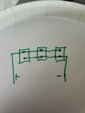
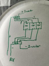
That's looking pretty good. The bus connections must be 4/0 for the Inverter, and AWG-4 for the "rest of the RV" leads. The individual battery leads should be at least AWG 2/0. You unfortunately have 5 wires, and most adequate bus bars have room for only 4.Also a paper plate drawing of my initial idea, no paper in the camper. Everything at the battery to 1 bus, and a small bus at the converter to put the combine things back at the converter.
Last edited:
Picture attached this time and as you can see, converter is already on its own breaker so that's a plus.
Everything I've read about microwaves on inverters really more dealt with the full running usage and not the power of the microwave. Still got some more reading to do there, it's down the road
If I don't have an empty spot for the inverter and had to double something would I be able to put 2 on 1 terminal? Those sizes would be tough.
So I would assume that I should size the bus based on the 3 batteries max output of 100 amps? So 300 total, bus a bit bigger than that.
Attachments
I feel that you should size above 400A if you're not using cable lugs pressed into the Inverter "input power" posts at high compression (my way, described just above the "- - -" in my earlier post #10. Done my way, you could avoid buying separate bus connectors - but the batteries would not connected on separate bolts at the Inverter, maintenance of just one battery pack would require removal of its fuse and disconnection its 12v supply and grounding wires.Picture attached this time and as you can see, converter is already on its own breaker so that's a plus.
Everything I've read about microwaves on inverters really more dealt with the full running usage and not the power of the microwave. Still got some more reading to do there, it's down the road
If I don't have an empty spot for the inverter and had to double something would I be able to put 2 on 1 terminal? Those sizes would be tough.
So I would assume that I should size the bus based on the 3 batteries max output of 100 amps? So 300 total, bus a bit bigger than I feel that you should size for that.
Done my way, you would have a total of 4 lugs attached on each Inverter post. 3 with 2/0 wires to batteries, one with AWG-4 back to the WFCO area. If the Inverter provides large brass lug connector bars, you could have 2+2 on both sides of each bar. If they are only 6mm or 8mm threaded bolts, then the lugs must stack on top of each other: There's a possible risk of the Inverter connecting bolts being too short to allow for all the 4 cable lugs AND the compression nuts together. (It depends on the Inverter.)
Inverter isn't happening right off, I'm mostly just trying to get the batteries in and working right now. I just don't want to have to redo too many things once I do go inverter, so I think I want to be oversized battery to battery, and bus bar. Inverter shouldn't have any bearing on the wire size back to the converter.
Just to confirm: You already have 3 batteries @ 100Ah each in hand? If not, you could likely save considerable money, and wiring hassles, and installation area, by buying or building fewer batteries with larger cells. (I have almost never recommended purchase or use of battery packs that "small").
You could possibly add the 4-AWG "fifth wire" lugs, for the 4-AWG cables (the ones going back to the WFCO area) on a "shared post" with one of the other cables in a 4-post bus bar, saving considerable money on the bus bars. "two terminals on one post" is generally a bad idea, and banned by NEC for the case of 120/240-VAC household wiring. In this scheme, you would put the lower current "4-AWG" lug above the high-current Inverter lug, so that it did not create an imbalance by being on the same post with a battery.
For the "strictly proper" case of building with longer bus bars (providing more than 4 terminals WITH at least 400A of current capability), you're probably looking at more than $100 each, as in this one: https://www.amazon.com/BLUE-SEA-SYSTEMS-POWERBAR-8-16/dp/B000MMDL6Q/.
Through a couple wierd turn of events I ended up with 2 "extra" batteries so I can either sell them or build a bank. 300ah should last us a weekend without the generator.
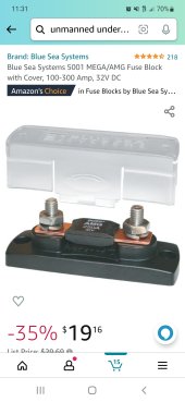
I'm looking at these fuse blocks with 125a fuses and these or similar for bus bar. Is there a better place than Amazon for this stuff?
Happy 4th!
I'm looking at these fuse blocks with 125a fuses and these or similar for bus bar. Is there a better place than Amazon for this stuff?
Happy 4th!
Attachments
Last edited:
The "mega" ANL fuse is slow-blow, you need a fast-blow "class-T" fuse on each battery (for the case when multiple LFP batteries are run in parallel). Advance warning: they are much more expensive. They should be sized slightly above the maximum PEAK current you wish to allow. Over at Amazon, these are a good choice, and a great deal while on sale: https://smile.amazon.com/Blue-Sea-Systems-225A-Class/dp/B000MMDLBG/. The matching fuse holders are kind of expensive, but avoid the need to build your own "project box" to contain the fuses and lugged connectors: https://smile.amazon.com/Blue-Sea-Systems-Class-Insulating/dp/B001VJ03LA/
The "300A" brass busbar is OK, although my approach (using much bigger brass connectors on a good Inverter) costs even less and allows for higher current capability. My own "3000/6000" inverter from eBay was super cheap, and I've run it quite hard in testing with pure resistive loads. The bolt holes on the big brass DC connector lugs are too close to the Inverter body, requiring that you "drill out" the bolt holes of typical "marine" tinned copper cable lugs to be bigger, with edges closer to the side or front edge of the lug (the position of the expanded hole varies according to the mounting direction of the cable). For this Inverter, you will need to drill the soft copper of the cable lugs, rather than the much thicker (and MUCH harder) brass of the Inverter connection lugs.
I have not stressed that Inverter with "reactive" loads larger than a 900-watt microwave, but it easily runs pure "resistive" loads (zero reactance, 100% power factor) of more than 2600 watts on a continuous basis. (In testing a new BMS unit, I ran a big toaster, and a tea-making water boiler, and some other small loads in parallel for more than 5 minutes.) Efficiency is very high, the exhaust (from one large fan) was only slightly above room temperature. The eBay seller only offers it via auctions, and it pairs with a somewhat expensive "remote". (Being a cheapskate, I built my own remote switch, using a cheap lighted switch with a separately purchased 3-pin airplane-type plug). It can't run an air conditioner without adding a more expensive "EasyStart" unit to the AC - but your 3 batteries wouldn't run an AC for very long anyway. Current auction: https://www.ebay.com/itm/394144642591
Last edited:
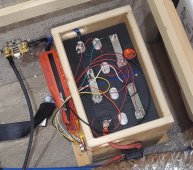
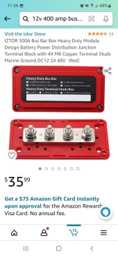
Ever run into a bus bar/fuse block like this for class t fuses? I won't skimp on circuit protection, but few parts is better/cheaper. For now, I am thinking about avoiding the microwave altogether and just powering outlets for tv/electronics charging.
Attachments
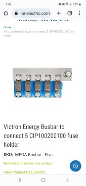
That runs mere 'Mega' fuses, rather than class-T fuses. If you're pretty sure that you won't have another accident, you could maybe use that -- but JK (for one) requires fast-acting class-T fuses when their BMS units will be used with parallel packs.
I know it's not the right fuses, have you ever run across something similar for the class t fuses? More than 4 positions, high enough amp rating... I'm actually surprised there's not more combined stuff for people running multiple batteries on the market.That runs mere 'Mega' fuses, rather than class-T fuses. If you're pretty sure that you won't have another accident, you could maybe use that -- but JK (for one) requires fast-acting class-T fuses when their BMS units will be used with parallel packs.
Similar threads
- Replies
- 4
- Views
- 561
- Replies
- 0
- Views
- 88
- Replies
- 3
- Views
- 498
- Replies
- 3
- Views
- 202