I have 4 405 12 v panels that I have to wire 2s2p to get 24v. Can someone show me how to calculate to find the wire size I need to go from panels to controller. I have attached pic from bk of one panel. I was on a site with all different formulas for calculating volts, watts and amps but can’t find it now. Thanks


You are using an out of date browser. It may not display this or other websites correctly.
You should upgrade or use an alternative browser.
You should upgrade or use an alternative browser.
Wire size
- Thread starter Revid
- Start date
Bluedog225
Texas
- Joined
- Nov 18, 2019
- Messages
- 2,921
Welcome.
It would be really useful for you to learn the formula. Watts=volts * amps.
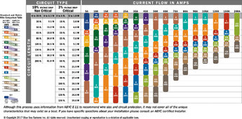
There is a wire ampacity chart by blue sea on the internet that will help you determine wire sizes.
There are some other things to know about not exceeding the volt limits on the controller. And volts go up in cold weather.
more info about your system would be helpful
It would be really useful for you to learn the formula. Watts=volts * amps.
There is a wire ampacity chart by blue sea on the internet that will help you determine wire sizes.
There are some other things to know about not exceeding the volt limits on the controller. And volts go up in cold weather.
more info about your system would be helpful
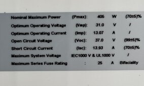
Your spec’s:
Voc 37v
Vmp 31v
Imp 13.07a
Volts * amps = watts
Going in 2s2p
Voc = 74v (you should be good as long as your solar charge controller can handle 100v
when combining panels: (use Vmp and Imp)
In series- volts add - use the lowest amps
In parallel- amps add - use the lowest volts
(You have identical panels so you don’t have to worry about that - but the formula works the same if your panels are different).
First put them in series: V=31v *2 = 62v & 13.07a
Then put two strings in parallel A= 13.07 *2 = 26.14a & 62v.
Figure out the watts - 62v * 26.14a = 1620w
With 26.14a - use #10awg wire between the panels and the SCC. #10 wire will handle 30amps.
You could use #8awg wire . If you think you might ever add a 3rd string in parallel- put in the #8.
Now that’s what I was looking for. Excellent Rocketman. I have been given so may different answers it’s not funny!! Now if I was to put in some breakers what size would I use? I have #2 wire between batteries. What size would you recommend between batteries and inverter and controller? It would not be more than 3-4 ft. Btw from panels to cc would be 15-18’ max . Did you see that chart from blue sea?. Again thanks
Attachments
Last edited:
I have 4 panels like in the pic above/ below. Going with a 3000 pure sine inverter and a 85a controller. Panels to Cc is 15-18’ . 6 125 ah 12v agm batteries that I have to wire to 24v. It’s going to be 24v system. Anything I missed??Welcome.
It would be really useful for you to learn the formula. Watts=volts * amps.
There is a wire ampacity chart by blue sea on the internet that will help you determine wire sizes.
There are some other things to know about not exceeding the volt limits on the controller. And volts go up in cold weather.
more info about your system would be helpful
Remember the fuse is to protect the wire - not the device.
I believe the breaker/fuse size is just above the wire size -
so with the #2 awg for batteries 125a max
For the inverter cables - probably 2/0 cable w 200a or 250a fuse (what does the manual for the inverter call for?
Because you will have three 24v batteries- it may be best to land them on a battery bus bar. (Look at Victron PowerIn also see YouTube how to add fuses).
From the battery bus bar the negative line should have a shunt based battery monitor (like Victron Smartshunt or BMV712), the positive should have main fuse and a power switch. Then you should land those cables on a distribution bus bar. (Maybe another PowerIn), the inverter, Solar charge controller, and another other loads& chargers go here. Anytime you go to a smaller wire it needs fused.
Also, if you get the Victron Smartshunt or BMV712 - it can read the battery mid-point. Read up on that… basically over time your 12v batteries will get out of sync electrically. You need to know when it happens and fix it by recharging the batteries to full at 12v.
Good Luck
I have 6 125ah 12v agm batteries or you meant when I have them in series it will give me three 24v? I have a battery disconnect switch coming. So #2 wire controller to battery with a 125a fuse/ breaker, #2 for inverter to batteries with a 200 or 250 fuse/ breaker. Iam trying to picture all this in my head. Lol
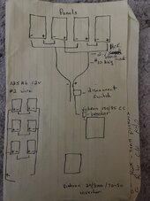
Don’t just picture it in your mind.
Draw out your plan - put everything in it - components, wire, wire size, fuses/breakers,etc.
Then post it back here. It is easy to miss things and mess them up when we just use words… less mistakes happen when you have a drawing and much less mid-understandings.
I might(will at some point) make a mistake- having a good drawing lets many more participate.
First, you are installing a bigger solar charge controller than is needed for your current project (do you have expansion plans?.
For 24v system the mppt 150/85 can handle 2400w of solar (you only have 1600w)
A 150/70 can handle 2000w
A 150/60 can handle 1720w.
The 150/60 is probably a lot cheaper and will still provide all the power you can produce. You could drop to a mppt 100-50, but you would be clipping your power at 1400w. Which is probably fine because your panels will probably never produce that much because they are flat mounted.
Second, read Victron’s “wiring unlimited” your batteries need the + on one side of the bank and the - on the other side. Or the batteries attached to a bus bar (which is what I would do with three sets).
Third, you need a shunt based battery monitor - Victron Smartshunt or BMV712. Read up on the mid-point monitoring. That way you can know when the two half’s of the battery start to get off.
You have a good start on your drawing- but it is not complete yet - keep filling it in. Will you have a distribution bus bar to combine all your loads?
Thanks again Rocketman. I had Victron tech check my specs and that’s what he suggested. I will look at the price of the 150/70 or 60. Can you send me drawing of the bus bar setup and or links to what I would need? If I only need the 60 or 70 that’s what I’ll get? The money I save I can buy a smart shunt. If you had to “design “ this setup can you show me what I would need ? Pm me??First, you are installing a bigger solar charge controller than is needed for your current project (do you have expansion plans?.
For 24v system the mppt 150/85 can handle 2400w of solar (you only have 1600w)
A 150/70 can handle 2000w
A 150/60 can handle 1720w.
The 150/60 is probably a lot cheaper and will still provide all the power you can produce. You could drop to a mppt 100-50, but you would be clipping your power at 1400w. Which is probably fine because your panels will probably never produce that much because they are flat mounted.
Second, read Victron’s “wiring unlimited” your batteries need the + on one side of the bank and the - on the other side. Or the batteries attached to a bus bar (which is what I would do with three sets).
Third, you need a shunt based battery monitor - Victron Smartshunt or BMV712. Read up on the mid-point monitoring. That way you can know when the two half’s of the battery start to get off.
You have a good start on your drawing- but it is not complete yet - keep filling it in. Will you have a distribution bus bar to combine all your loads?
Last edited:
For bus bars - if they will fit- look at the Victron PowerIn. (Look for a YouTube video about adding fuses to them).
I would have one PowerIn (w/fuses) connecting to the batteries, then on the negative side the Smartshunt/BMV712, and the positive side a fuse and master shutoff switch, then they go to another PowerIn w/fuses that has your inverter wires, Mppt wires, and any other loads. (24 to 12v converter?).
I would have one PowerIn (w/fuses) connecting to the batteries, then on the negative side the Smartshunt/BMV712, and the positive side a fuse and master shutoff switch, then they go to another PowerIn w/fuses that has your inverter wires, Mppt wires, and any other loads. (24 to 12v converter?).
fromport
Solar Addict
Your batteries should be hooked up like this:First, Merry Christmas, I have attached a pic of what I have so far. Would like some input into fuses/ breakers and how to wire. Thanks

Don’t think I can get bus bars to fit cause of size of battery. I have 16” 2/0 cables now connecting batteries so would like to use most of them if I could. I can see using three but will have to figure out something else for “long” sides. Master switch on positive side?? I will put a fuse going to inverter. What size you think?For bus bars - if they will fit- look at the Victron PowerIn. (Look for a YouTube video about adding fuses to them).
I would have one PowerIn (w/fuses) connecting to the batteries, then on the negative side the Smartshunt/BMV712, and the positive side a fuse and master shutoff switch, then they go to another PowerIn w/fuses that has your inverter wires, Mppt wires, and any other loads. (24 to 12v converter?).
What wire size does Victron ask for in the Multiplus manual? Use that or larger for your inverter wires and the “backbone” wires. (Probably 2/0) - it also tells the fuse to use.
The wires for the mppt depend on which model you pick (which is the amps it can deliver).
50a- #6
60 -70 - or 80 #6 or #4
Use the fancy Blue Sea wire chart you found above - if the equipment you buy does not give a Recommendation.
The wires for the mppt depend on which model you pick (which is the amps it can deliver).
50a- #6
60 -70 - or 80 #6 or #4
Use the fancy Blue Sea wire chart you found above - if the equipment you buy does not give a Recommendation.


Don’t use that as a buss bar…
Cons:
Thin brass bar (much higher resistance than copper.
Pros: cheap (or is that a con???).
It does have plastic covers.
Find a tin plated copper busbar - Blue Sea - Victron PowerIn. Make sure the bus bar is 1/4” thick.
Cons:
Thin brass bar (much higher resistance than copper.
Pros: cheap (or is that a con???).
It does have plastic covers.
Find a tin plated copper busbar - Blue Sea - Victron PowerIn. Make sure the bus bar is 1/4” thick.