diy solar

diy solar

Fuse and wire size ok?

kwest364

New Member
Joined
Jun 13, 2023
Messages
22
Location
Santa Barbara, CA
I have 4 x 12V 100Ah LiFePo4 batteries. Wired in series for 24V 200Ah. Batteries have 100A/1C discharge rate (LiTime brand).

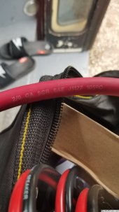
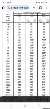
So my breaker/shut off switch should be DC rated at 250A or 225A correct? 200 x 1.25 to allow for safety margin puts me around 250A, but 225A might be better due to lower threshold? I have 2/0 wire 105°C/220°F insulation, SGR wire from NAPA Auto. Ampacity charts seem to rate it up to around 325A. Call it 300A. (Pic attached)

Can I use a bolt on MRBF fuse? To simplify and make things cleaner? Forums seem to say for 24V systems, those are fine and safe to use.

Have 3000W inverter. Lynx distributor.

What size shut off switch to use? One that matches battery bank fuse I'm guessing? (225A or 250A) Or does this one not matter as much as long as I get a rated one for equal to or higher than 225/250A? I'm assuming I can bolt fuse straight into/on cut off switch. So battery bank to fuse, to cut off switch, all bolted together without needing to do wires and lugs.

Order of operations: battery bank(200A/24V) ---> 225/250A T or MRBF fuse --> cut off switch--> inverter (3000W/24V) --> lynx distributor. I got that order of operations right? All using 2/0 cable?
 

Attachments

  • 20231019_101919.jpg
    20231019_101919.jpg
    447.7 KB · Views: 13
The inverter will dictate the total amperage being pulled from the battery bank. So is the 24v 3kw inverter all that’s going to be running on the system?
 
2/0 copper ampacity is 145A...
According to what chart? Everything I've seen is over 200A. Blue sea Systems circuit wizard says 2/0 rated up to 285A, the colored chart Blue Sea uses and in Will videos says 2/0 good for 200A out to 20ft round trip, but perhaps my settings are wrong? 24V, 200A, 6ft round trip run (closer to 4ft or less really), <3% drop, variable load, 105° C, 60min duration, terminated on fuse, 200A CCA, main circuit. And that gets me 0 AWG, so I figured 2/0 would definitely be ok.

What size to use? 4/0?
 
The inverter will dictate the total amperage being pulled from the battery bank. So is the 24v 3kw inverter all that’s going to be running on the system?
Should be. For a skoolie system. I'm going to use a 24V to 12V step down converter for 12V DC loads (water pump, suburban propane furnace, 6gal water heater, maybe a roof fan).

Is that what you meant?
 
Should be. For a skoolie system. I'm going to use a 24V to 12V step down converter for 12V DC loads (water pump, suburban propane furnace, 6gal water heater, maybe a roof fan).

Is that what you meant?


Essentially yes. So if your inverter’s max load is the 3kw divided by the nominal voltage of your battery, you shouldn’t be over 120 amps of total pull on the batteries.
 
Essentially yes. So if your inverter’s max load is the 3kw divided by the nominal voltage of your battery, you shouldn’t be over 120 amps of total pull on the batteries.
But wire and fuse off battery bank should be sized and fused for 200+A, correct? Bigger wires and fuse and cut off switch pre-Lynx (from battery bank), and smaller wire and fuse (already in Lynx distributor) post-lynx (to inverter)?

And again, separate fuse (mega fuse in lynx distributor) for inverter?

Don't I need to add 25% fuse headroom, and inverter efficiency loss of 10%? So:
3000W ÷ 24V = 125A
125A x 1.25 = 156A
156A ÷ 0.9 = 173 A, round up to 175A fuse and wires ampacity rated above that?
 
2 xb12V batteries with 100a discharge in series is still only going to provide 100amps but at 24 volts, you will need more batteries if you want to be able to run that inverter at full power. EDIT: Ignore this part I misread your first post.

Your battery fuse and wiring from the battery to the distributor, needs to be sized for both inverter and dc/dc converter size. Inverter fuse for 3000w at 24 volts is recommend at 300 amps, and 4/0 wire is recommend.
 
Last edited:
According to what chart? Everything I've seen is over 200A. Blue sea Systems circuit wizard says 2/0 rated up to 285A, the colored chart Blue Sea uses and in Will videos says 2/0 good for 200A out to 20ft round trip, but perhaps my settings are wrong? 24V, 200A, 6ft round trip run (closer to 4ft or less really), <3% drop, variable load, 105° C, 60min duration, terminated on fuse, 200A CCA, main circuit. And that gets me 0 AWG, so I figured 2/0 would definitely be ok.

What size to use? 4/0?
 

Attachments

  • Screenshot_20231021_213150_Chrome.jpg
    Screenshot_20231021_213150_Chrome.jpg
    283.9 KB · Views: 35
So, that's
NEC Table 310.15(B)(16) (Formerly 310.16) that you screenshotted states: "Allowable ampacities of insulated copper conductors rated up to and including 2000 Volts, 60°C through 90°C (140°F through 194°F), Not more than three current-carrying conductors in raceway, cable, or earth (directly buried), based on ambient temperature of 30°C (86°F)."

According to above chart and conditions:
2/0 = 145A @ 60°C

VS

NEC Table 310.15(B)(17) (Formerly 310.17) which states "Allowable ampacities of single insulated copper conductors rated up to and including 2000 Volts in free air, based on ambient temperature of 30°C (86°F)."

According to above chart and conditions:
2/0 = 225A @ 60°C


Now, my wire has 105°C rating, so even under the lower ratings of lower rated chart, ampacity should be over 200A. Under the higher ratings of higher rated chart, ampacity is well over 300A, call it 325A. And 2nd chart (310.15(B)(17)) with single runs in free air are well over 200A, especially with 105°C insulation rating, which is over 300A. The 2nd table with higher ampacity seems to match my use case, correct? No bundles, or conduit, or burying.

Why isn't higher ampacity capability of my insulation rating being taken into considerstion?


According to 1st chart you screenshotted (310.15(B)(16), I'd need wire size of 250KCMIL. Trying to understand here. I think I'm getting too far into the weeds.
 
2 xb12V batteries with 100a discharge in series is still only going to provide 100amps but at 24 volts, you will need more batteries if you want to be able to run that inverter at full power.

Your battery fuse and wiring from the battery to the distributor, needs to be sized for both inverter and dc/dc converter size. Inverter fuse for 3000w at 24 volts is recommend at 300 amps, and 4/0 wire is recommend.
I have 4 batteries, 2s2p. So that's 12V @ 400Ah, originally, and when in series is 24V @ 200Ah. I'm not sure what you mean.

Bear with me please haha
 
Last edited:
Since as you mentioned in a follow up post this is skoolie build, the requirements of the NEC don't strictly apply and there aren't any official standards that apply, but using a standard is a good idea for a well built system. You can choose to use the NEC or the marine standards in Blue Sea charts and tables.

To use the free air ratings per the NEC cables need to exposed on sides for there run and in a ventilated space, which might be hard in a vehicle build. Also one issue with higher temperature conductors, is the ratings of the terminations, will the devices the wires are connected to handle the heat of 105c wire. The NEC has rules that limit wire ampacity to the 60c or 75c unless terminations are labeled and rated for higher temperatures. Wires over 1/0, per the NEC, can be run in parallel which is one way to avoid needing to use really large cables.
 
So 2/0 would be fine to use for my purposes? Between batteries, battery bank to lynx distributor, and lynx distributor to panel?

Battery bank fuse = 200A, 225A, or 250A? 225A I'm leaning towards as middle ground. Mrbf bolt on ok to use, but T class is preferred as best thing on forums. Mrbf saves space and I like bolt on directly for simplicity.

Sounds like gist is:
To be really sure, to use 4/0 for battery bank to distributor, and 4/0 from distributor to inverter, and 2/0 for inverter to DC/AC panels.
 
Back
Top