diy solar

diy solar

What gauge wire and fuse for 48v battery and 48/3000 inverter

beowulf

New Member
Joined
Feb 25, 2023
Messages
77
Location
USA
So I read all the links that popped up regarding this and they are all for 12v and couple for 24v which if I read correctly from other posts 12v uses much thicker wire than 24v and 48v is even smaller. However, I want to be sure before I finish my battery and wire everything up.

I have the Victron 48/3000 inverter/charger. I am building a 48v 16s (Jehu Garcia battery/videos/etc) using the LEV60 72ah batteries. The BMS is 100a.

Internally I think Jehu's video was using 4awg but hard to tell and I did wire up some 4AWG in the bms/battery but MAN that stuff is difficult to bend around the small space. So I did order some 2 gauge welding/battery cable (copper, not CCA) which has a ton of tiny strands. I'd rather have "more" than worry about heating/fire/etc. Also appears 2AWG can handle up to 130amps, so I think it should be plenty for the internal of the battery.

Where I am a bit more hung up is on the cable AWG size to run from battery to the inverter. I actually sprung for the Lynx Distributor as I do want to add MPTT as well as another group of 48v batteries at some point (though I am unclear if I can add other brand batteries using the distributor to the same inverter/charger or if I need a separate inverter/charger and lynx distributor setup if I say.. build some 302ah battery kits).

Because the BMS is 100a, and the length from battery to the distributor, and then distributor to battery is only a couple feet each at most, I assume 2AWG is still enough for a 48v setup. The inverter puts out 3000w max.. which means a max of 25a on the AC OUT.. so I dont see why 2AWG wouldn't be enough if not overkill. As for charging the battery, presently I will only have a 15a AC IN (via 12awg plug) to charge it. Once I add MPTT and solar, maybe then if necessary I could wire up 2/0 if needed from inverter to battery?

So.. just wanted to quadruple check my assumption that a 2 AWG should be fine for my current uses which is 15a AC IN to charge, and at most 25A 3000watt output via AC OUT 1 (also on 12AWG plug).

Thanks.
 
2 AWG is very close to 35 mm2

Screenshot_20240313_152758_Samsung Notes.jpg

Make sure you enable power control at 15A before connecting AC input otherwise it will start pulling 35A@~58V to charge which might be hot for your setup.
 
2 AWG is very close to 35 mm2

View attachment 201945

Make sure you enable power control at 15A before connecting AC input otherwise it will start pulling 35A@~58V to charge which might be hot for your setup.
Oh very cool.. I didn't see this or missed it! So up to around 15 feet in length I could handle 2AWG.

So the one thing I can't seem to figure out is where I attach cables from inverter to the distributor. I assume the inverter goes on the end +/- and the battery attaches to one of the 4 ports with 125a fuse across the pos? I also apparently need to put a fuse between the pos inverter to distributor?

Also a little confused with regards to the max AH limit. Is that due to the amount of current to charge (or pull) that could occur with larger AH capacity? For example, I want to build about 6 of these 72ah battery setups, run them in parallel using bus bars. That would put me at about 432ah total. But if I build a set of 302AH x 16cell batteries.. then.. that means a single inverter for one bank of batteries? Is that pretty common if I were to build a couple of 16cell 302ah batteries to run an inverter for each? Mind you.. this is all speculation right now as to if/when I could look to build larger batteries. For now, I am going to have just 2 of these 72ah 48v rack mounts. I was considering 6 in total.. but the overall price is a bit higher than EG4 battery options.. and SOL batteries. And with Sodium Ion batteries coming soon (assuming these inverters would work with them as well) I would hope to see more cost friendly battery options in the next year or so.
 
Usually the battery bus would connect to the positive end of the distributor, with appropriate fusing/breaker/shutoff. Then on the negative back to battery the shunt would be placed in between to track your battery state of charge. Then inverter would get something like a 70V 125A mega fuse and connect to one of the four distributor posts.

 
If you have multiple inverters paired together in the future, you want them to be drawing from the same battery bank. You don't want them seeing a voltage imbalance which you would get if you had seperate banks for each inverter. Now that doesn't mean you can't have a bunch of batteries making up that bank.
 
Usually the battery bus would connect to the positive end of the distributor, with appropriate fusing/breaker/shutoff. Then on the negative back to battery the shunt would be placed in between to track your battery state of charge. Then inverter would get something like a 70V 125A mega fuse and connect to one of the four distributor posts.

How would that work if you have 2 or 3 different battery setups though? Or can you not mix different AH/WH 48v battery banks using the Distributor? I assumed part of the point of the 4 posts were to handle multiple power sources, e.g. MPTT/solar, multiple batteries, etc.. and that the end (if not attached in a line with another Lynx device) would be going to inverter so that mptt/batteries all combined? Not saying you're wrong by any means, but if you have 2, 3 or more banks, then I guess that means each has to have their own inverter even if they aren't near the AH capacity of the inverter? That would then tell me the distributor is more about adding solar to charge battery with vs supporting multiple battery banks?
 
So usually the distributor (or modded power in) is used for the loads (inverters, charge controllers, with suitable fuses). Then you would connect a power in (where the parallel battery connections go), with smart shunt or lynx shunt between them. You can certainly connect to your batteries direct to the distributor posts, but you won't be able to use the smartshunt to calculate soc that way.
 
So usually the distributor (or modded power in) is used for the loads (inverters, charge controllers, with suitable fuses). Then you would connect a power in (where the parallel battery connections go), with smart shunt or lynx shunt between them. You can certainly connect to your batteries direct to the distributor posts, but you won't be able to use the smartshunt to calculate soc that way.
Interesting. OK. Well I did get the 500a battery monitor which I thought goes between the Distributor and battery NEG cable to give me details on the one 48v battery bank I have. I don't know if there is some way to tie in that China BMS to the Victron app, doubt it. So I got the distributor vs the power in because I assumed it was better because it had the fuse option per post. So I figured my wiring would have the inverter pos/neg to the end posts on the distributor with a fuse AND on/off switch between the inverter and the Distributor post (not sure if it matters if fuse is on pos or neg side of things). Then one battery (for now) on a post with 100a fuse (since BMS on battery is 100a), eventually a 2nd post would be MPTT with solar input, and if I build a set of 302ah (or buy EG4 batteries) being different brand, would use another post with fuse on that. Though I did question how the heck the MPTT attached to the same bus bar as the batteries somehow go in to the inverter and then back down (along the same wires) to charge battery.. or if it just directly bypasses inverter and feeds batteries directly.. but then you wouldn't be able to run on solar (if you had enough) if it only went to batteries. So wasn't sure how the input from the MPTT doesnt "flow down" to the battery being attached via the Distributor bus.

What I have yet to find is an image/drawing of a typical 48v/3000 (or 5000) showing the right (only/best) way to wire things up. I seen a few for 12v and assumed its the same, but those are typically somewhat different applications. For me, I am just powering my office equipment so this whole setup is on a shelf in my office.. because I run a few bits of gear that with day time peak charges, cost me about $125 a month to operate. Figured with battery and off peak charging, would drop my bill in half or so given off peak rates are a bit less than half of peak.
 
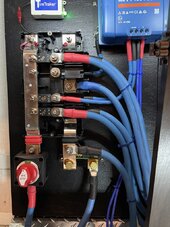
Yes, the smart shunt will connect between negative bus bar and battery negative, like this.

The bus is connected to the batteries, sccs and inverters. The batteries draw the power from the bus, the sccs feed the bus. The power doesn't go to the inverter first and then to battery for charging. Direct from SCC to battery. The inverter will supply to the bus for battery charging it you have an external source, and draw for inverting.


52464647874_5b9737658c_b.jpg
 
Yes, the smart shunt will connect between negative bus bar and battery negative, like this.

The bus is connected to the batteries, sccs and inverters. The batteries draw the power from the bus, the sccs feed the bus. The power doesn't go to the inverter first and then to battery for charging. Direct from SCC to battery. The inverter will supply to the bus for battery charging it you have an external source, and draw for inverting.
Oh this is a cool setup thank you for sharing. Ok I think I am getting the general idea. So on the POS side I see you have the switch, is there a fuse ALSO (not shown) going to the battery (and is it on pos or neg side.. shouldnt matter I dont think)?
In the pic you have the Victron battery shunt (monitor?) right on the neg end there.. so I assume that then goes to battery (obviously). But what is the 2nd wire coming off before the shunt? I assume that is cause you ran out of posts (4 total) and are you using that for something as well.. but I ask because I don't see a separate pos lead.

So one set of wires goes to the inverter. Another is for the MPTT (I can see those). Not that it matters probably but I see another set of wires as well. Just curious with one going to inverter and another to MPTT what else would you run a set of wires from the Distributor to?

And I apologize again for asking this.. but if you have the ends going to one battery bank.. and you wanted to add more battery, I assume the right way is to put those in parallel using bus bars (ideally.. though I seen some cabled to one another as well) (e.g. they would all be 48v but perhaps different AH capacities.. or should you never mix AH capacity as well.. if so use a separate inverter/distributor setup?)?

Seems it's hard to find a decent picture of a multiple battery setup with possibly different battery capacities, multiple inverters, distributors, etc. So thank you for your help.
 
Yeah that's not my picture just an example, and not sure why he's tapped off before the smart shunt on the negative there. I'm guessing that 100A fuse is another SCC.

You can have different batteries of different sizes, assuming same chemistry and voltage (LFP etc), all on the same bus.
 
So you can either parallel all the batteries at the battery end, or run them into a separate power in. Then it would look like this:

Screenshot_20240313_165503_Gallery.jpg
 
Just a side note, don't rely on mega fuses to break a high AIC short circuit current from an LFP bank @ 48V, they are fine for 'normal load' overload. That means either a T Class on each battery or NH fuse disconnectors.

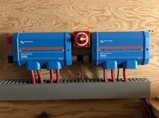
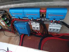
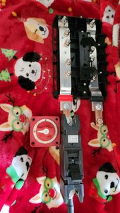
I have Mersen 250A NH Disconnectors for each battery going into my Power In's, with smartshunt in between batteries and loads, similar to the @Brucey's setup.

IMG_20231222_142556_495 (1).jpg

IMG_20231221_123801_796 (1).jpg
 
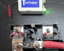
These tiny wires running under the fuse and other bolt-down items concern me. They're not fused and they won't pop any of those indicated fuses. Should reroute or put a suitable fuse on them.

1710376009972.png
 
Just a side note, don't rely on mega fuses to break a high AIC short circuit current from an LFP bank @ 48V, they are fine for 'normal load' overload. That means either a T Class on each battery or NH fuse disconnectors.

I have Mersen 250A NH Disconnectors for each battery going into my Power In's, with smartshunt in between batteries and loads, similar to the @Brucey's setup.

View attachment 201986

View attachment 201987
That was just an example, but I've gone with a 250A 150V DC breaker from Midnite.

20240313_135109.jpg
 
Man.. I tell you what.. when setting up a DIY setup like this, there are all sorts of extra costs nobody mentions. LOL.

So, given that my one 48v bank is 100a BMS, would a 100a NH be enough? I'd assume I would put that on the pos terminal right before the end of the Distributor (where you have your circuit breaker above picture)?

Are these: https://www.amazon.com/gp/product/B075L69WPR/ref=ppx_yo_dt_b_search_asin_title?ie=UTF8&th=1
any good? The max there is 100a, but curious if something like that at 100a is ok to use or not good at all?

So if I have this right.. I would have a fuse (of some sort) + the on/off switch on the POS side between the distributor and battery. The NEG would have the battery shunt (I got the 500a one) between the distributor and battery. That shunt would connect to the Cerbo GX via the little cable I think. Then I would have the inverter/charger using 2AWG wire (for now anyway) connect to one of the 4 poles on the distributor and I dont recall what size fuse and/or which I should get to lay over the POS terminal on that pole??

The above wiring (2AWG from distributor end to battery as well) would be enough to charge the battery using the AC IN on the inverter, and power the AC OUT 1 up to 3000 watts from the battery, yah? I assume once I had an MPTT that will also power whatever I need and if there is MORE solar coming in that I consumer at the inverter, it would also charge the battery? Not entirely sure how all that direction of current works since it seems like the battery and the inverter are connected to the same bus.. I must be missing something with how it can send power to the inverter (from solar) but any excess goes to charge the battery.

I got the 48v/350a switch as well.

When I add a 2nd (or more) battery, I would swap the 2AWG with 2/0 or 4/0 and if possible 4/0 to ensure less heating/loss with having more cable than I need right.. as opposed to 2AWG being perhaps just enough but heating up thus some loss with heat.

Anything I am missing? I assume the Cerbo GX via the network cable and such sees/manages/controls the inverter, the fuses/etc on the distributor (e.g. indicators they are or are not blown), the shunt, and I also have a 48v to 24v DC inverter as I have a Ecoflow River 2 Pro I'd like to charge and use as well. Not sure where that would go but perhaps on one of the poles on the distributor as well?
 
Yeah 2awg is what Victron recommends, you won't need to upsize that if you add more batteries, as demand from inverter will be the same (the fuse/breaker protects the wire).
 
Back
Top