diy solar

diy solar

same post inverter burn out

fire hazard

New Member
Joined
Jul 14, 2021
Messages
160
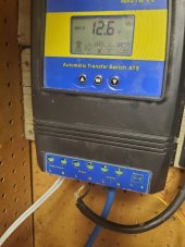
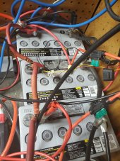
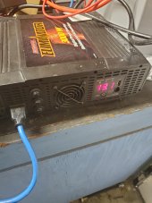
i dont know whats going on,2 1000w inverters fried,now using 3000w eliminator 12v,this one shuts off before damage occurs,error opp means ac short circuit,using 420w on a 3000w inverter,im at a loss,3 gell batteries in parallel 51ah,please help.12.2v switches over to mains reconnects at 14v,appliance 2 lights
 
think we are talking either batteries or transfer switch what else could it be runs fine on mains so no short,just thinking could the batteries be drained to fast,cloud shows up lasts maybe 20mins
 
That’s mostly what I was looking for.

What is all the other stuff, especially the alligator clamps?
clamps tempery until i figure this out they go to the controller,white wire on transfer switch plugs into mains,black wire goes to lights and the blue one plugs into the inverter
 
So once solar isn’t charging the batteries, how long does it take for the voltage to go from 13.5v to 12.5v and the ATS flops over?

Also why does the SCC show 13.79 yet the ATS show 12.6v, shouldn’t they read the same?
 
So once solar isn’t charging the batteries, how long does it take for the voltage to go from 13.5v to 12.5v and the ATS flops over?

Also why does the SCC show 13.79 yet the ATS show 12.6v, shouldn’t they read the same?
takes about 20mins for batteries to get to 12.2 then flips voltage constantly changing sun just wont cooperate,need a fan for the clouds also
 
So once solar isn’t charging the batteries, how long does it take for the voltage to go from 13.5v to 12.5v and the ATS flops over?

Also why does the SCC show 13.79 yet the ATS show 12.6v, shouldn’t they read the same?
interesting just checked transfer switch 12.4 controller 13.6,but the transfer switch is getting its reading from the middle battery,just checked the voltage all three batteries 13.1,transfer switch reads 12.4,you got me scratching my head,wtf,inverter 12.8
 
Last edited:
Some lower end inverters do not electrically isolate the AC output from the DC input, and both of the AC outputs are hot with respect to the DC input. They also don't have overload protection. The result is if either of the AC output conductors are connected to either of the DC input lines, the inverter goes up in smoke. The most common way to create this situation would be adding a neutral-ground bond to the inverter's output. It's just a product of the very lowest cost way to build the inverter. They're meant to have only individual devices plugged directly into the inverter outlets.

Of course, you could just simply be short-circuiting the output, smoking the inverters without protection.
how can i protect the inverter,cost me 400 bucks been running all day,shut down with the error opp this morning when it would be switching back and fourth more often
 
Last edited:
Some lower end inverters do not electrically isolate the AC output from the DC input, and both of the AC outputs are hot with respect to the DC input. They also don't have overload protection. The result is if either of the AC output conductors are connected to either of the DC input lines, the inverter goes up in smoke. The most common way to create this situation would be adding a neutral-ground bond to the inverter's output. It's just a product of the very lowest cost way to build the inverter. They're meant to have only individual devices plugged directly into the inverter outlets.

Of course, you could just simply be short-circuiting the output, smoking the inverters without protection.
hey what if one of the load wires were reversed
 
are you deep in thought mistersandals
Are you referring to me stepping away for a bit?

I am unsure what the problem is.
when it switches back and fourth the lights dont even flicker
I don’t understand what back and forth you are referring to. The ATS switch?
It switches from battery to grid and back to battery?

It’s a good sign that your ATS switches seamlessly.

I think 740GLE might be onto something regarding voltages.

I am not sure how several inverters could work and fail the same way.

Sorry, wish I had more.
 
how can i protect the inverter,
I think it would take somebody knowing more details about your AC load to answer that. If it might help, here's a quick description of how the cheap MSW inverters work. They first upconvert the DC input to about 140 volts DC (for a 120 volt RMS output). The minus side of this 140 volts is tied (hardwired) to the negative battery input. Then at the output frequency, the inverter reverses the polarity of the 140 volt DC on the AC output terminals, creating a 280 volt peak-to-peak waveform. The AC outputs are at zero volts for the mid-step of the MSW waveform. This, each of the two AC output lines is sometimes connected to the DC negative input, and sometimes connected to the positive output of the 140 volt supply. If the DC input is connected to a common or ground wire, connecting either AC output line to common or ground results in the 140 volt DC supply being short-circuited, and the transistors that perform the polarity switching go up in smoke. (I did learn this the hard way). That 140 volt value of the DC supply is nominal. It's unregulated and proportional to the voltage of the inverter's DC input. The RMS output voltage is regulated by changing the pulse width of the PSW waveform. As the battery voltage goes down, the AC peak voltage goes down, and the width of the active part of the waveform increases. If you have something really, really weird going on, maybe the differing peak output voltage and/or pulse width could be related. A longshot I realize. You might not appreciate my opinion, which is to get a decent quality PSW invcerter.
 
Back
Top