diy solar

diy solar

Seplos V3 BMS No Port COM Connection

...Ghost...

New Member
Joined
Jun 19, 2024
Messages
9
Location
Dublin, IRL
Hi All,

First time poster here and glad to have found this site.

I have built my first Seplos Mason with the V3 BMS and active balancer from FogStar in the UK. After building it, I powered the unit on and for a couple of days, there was no issue while I was waiting for a USB to RS485 convertor and an ethernet crimper kit. In the interim, the LCD screen failed and upon investigation I found patchy and missing solder joints on the LCD and LED PCBs. I found some raised seats on the BMS (1 seat is raised 1mm from the board surface), but only the LCD seemed to have failed due to a failed solder joint. FogStar have been good and I am told that new LCD and LED boards are on the way after I provided details. That's not the reason for this thread, but I added it because it may be relevant to my current problem (no pun intended). I don't believe the PCB issues are related to the following problem...no COM port showing.

I received the USB to RS485 converter and crimper kit. I made up a 3 line cable with PIN 1, 2, 3 going to B, A, GND respectively. I downloaded the BMS Studio and connected the cable. I tried both RS4851 and RS4852. I can't connect. I am prompted to select a port, but the option is blank. I cannot manually enter com 5, or any other number/character directly or on the settings popup. I tried changing from the 19200 baud rate to all other options, but this makes no change. Only the power light on the USB converter is active. The RXD and TXD lights stay off. I did see another thread here (from 2022 on a V2 Seplos BMS) where someone switched the A & B lines and it worked for that person. I tried this and the RXD light came on when I turned on the battery pack, but I still could not connect, or see any available COM.

Has anyone seen this problem before, or do you have any suggestions? I have not connected the battery to my inverter at this stage, as I want to configure the battery first.
 
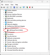
First make sure your computer recognizes the RS485 gdangus. Most show up immediately, others may need a driver installed. Check in the device manager for a new USB serial port to show up when you plug it in.
mmc_1IHUjXm3jC.png

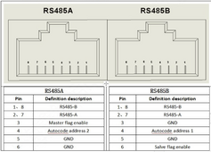
Second, there is some confusion on the port wiring for the 2 RS485 ports on the BMS as not all documents agree. This seems to be correct for the Seplos V3 BMS:
1718851006947.png
I chose to use 1&2 for RS485-A&B and 5 for GND. That way I can connect via either physical port.

Bonus tip if you get this working: if you have grabbed the recently released BMS Studio V2.0.0.1 from Seplos, you will find the configuration password stored on line 9 of the XML file named DevBMSStudio.exe.config. Change it at will.
 
First make sure your computer recognizes the RS485 gdangus. Most show up immediately, others may need a driver installed. Check in the device manager for a new USB serial port to show up when you plug it in.
View attachment 223266

Second, there is some confusion on the port wiring for the 2 RS485 ports on the BMS as not all documents agree. This seems to be correct for the Seplos V3 BMS:
View attachment 223267
I chose to use 1&2 for RS485-A&B and 5 for GND. That way I can connect via either physical port.

Bonus tip if you get this working: if you have grabbed the recently released BMS Studio V2.0.0.1 from Seplos, you will find the configuration password stored on line 9 of the XML file named DevBMSStudio.exe.config. Change it at will.
I can confirm, I use 7 and 8 for my comms with 5 as ground.
 
Your computer isn't configured for the usb dongle, has nothing to do with wiring, thats why there is not comm port to select from.

On Wiring, Ports ( female ) go from 8 to 1 and connectors ( male ) go from 1 to 8 left to right, I came across this just the other day with Seplos docs and they say "port" but is the connector and is easy to do backwards because of this.
 
First make sure your computer recognizes the RS485 gdangus. Most show up immediately, others may need a driver installed. Check in the device manager for a new USB serial port to show up when you plug it in.
View attachment 223266

Second, there is some confusion on the port wiring for the 2 RS485 ports on the BMS as not all documents agree. This seems to be correct for the Seplos V3 BMS:
View attachment 223267
I chose to use 1&2 for RS485-A&B and 5 for GND. That way I can connect via either physical port.

Bonus tip if you get this working: if you have grabbed the recently released BMS Studio V2.0.0.1 from Seplos, you will find the configuration password stored on line 9 of the XML file named DevBMSStudio.exe.config. Change it at will.

Thank you and the others who pointed this obvious error out. I literally just purchased a new Laptop a few days ago (ASUS Viviobook) specifically for battery setup and for some reason, the dongle isn't working. It did show up in device manager, but in my haste, I hadn't spotted the warning symbol beside the icon and I carried on without checking properly!

I swapped out pin 3 for pin 5 on the GND (Thanks also for that) and used my home PC to connect with the dongle and I am now connected to the battery. Finally some progress.

Does anyone have the best recommended settings I should use? For a buffer, I think I would like to set the charge and discharge limits at 90% and 10%. Aside from that, what do people set their max and min cell voltages at? Any other tips would be most appreciated, especially if you have a Solis inverter!

I have a 5kW Solis Hybrid inverter. The battery is the 305Ah Fogstar sell. I have already ordered a second one from them and might even add a third one later this year. My house uses around 14,000kWh per year, with maybe 2,500kWh used on charging my EVs from midnight to 8am when the power is cheaper (about half price). This is when I will top up the batteries to supplement the solar in the darker days of the year.
 
Does anyone have the best recommended settings I should use? For a buffer, I think I would like to set the charge and discharge limits at 90% and 10%. Aside from that, what do people set their max and min cell voltages at? Any other tips would be most appreciated, especially if you have a Solis inverter!
I have Solises... and DIY battery pack with 280Ah cells. Set charge limit to 100% and discharge to 15%. Only setting charge to 90% will prevent the BMS from balancing as a high enough cell voltage is not reached.

I set my charge voltage to 3.45V per cell. BMS voltage limits are set (IIRC) to 3.55V and 2.8V, though BMS will report 15% and Solis will stop discharging before 2.8V is reached.

I have a 5kW Solis Hybrid inverter. The battery is the 305Ah Fogstar sell. I have already ordered a second one from them and might even add a third one later this year. My house uses around 14,000kWh per year, with maybe 2,500kWh used on charging my EVs from midnight to 8am when the power is cheaper (about half price). This is when I will top up the batteries to supplement the solar in the darker days of the year.
(y) we do that too - have avoided all peak rate elec usage for two winters now. The only limit you will have is the 5kW charge capability of the Solis, so depending on how long your cheap rate is for, you may not be able to charge up all three packs overnight.
 
First make sure your computer recognizes the RS485 gdangus. Most show up immediately, others may need a driver installed. Check in the device manager for a new USB serial port to show up when you plug it in.
View attachment 223266

Second, there is some confusion on the port wiring for the 2 RS485 ports on the BMS as not all documents agree. This seems to be correct for the Seplos V3 BMS:
View attachment 223267
I chose to use 1&2 for RS485-A&B and 5 for GND. That way I can connect via either physical port.

Bonus tip if you get this working: if you have grabbed the recently released BMS Studio V2.0.0.1 from Seplos, you will find the configuration password stored on line 9 of the XML file named DevBMSStudio.exe.config. Change it at will.

If you hold the "male" RJ45 connector (that fits into the above picture of the RJ45 / RS485 jacks) with the pins facing up and the locking tab away from you, pin 1 will be the leftmost pin and pin 8 will be the rightmost pin. Roll the male connector over with the locking tab up, insert in the above jack and the pin numbers will line up.
 
I have Solises... and DIY battery pack with 280Ah cells. Set charge limit to 100% and discharge to 15%. Only setting charge to 90% will prevent the BMS from balancing as a high enough cell voltage is not reached.

I set my charge voltage to 3.45V per cell. BMS voltage limits are set (IIRC) to 3.55V and 2.8V, though BMS will report 15% and Solis will stop discharging before 2.8V is reached.


(y) we do that too - have avoided all peak rate elec usage for two winters now. The only limit you will have is the 5kW charge capability of the Solis, so depending on how long your cheap rate is for, you may not be able to charge up all three packs overnight.
Cool. I was thinking about adding a charger to allow me to top up the batteries more quickly during cheap rate.

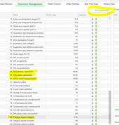
Would you mind checking this out for me. Just a couple of questions I am not sure about in the params.

1. When I change parameters, do I just select "Set Parameters" to send it to the BMS?
2. Line 89 and 90. This was default at 290. I changed to 305 to match the capacity of my cells. All OK there?
3. Line 91. This was set to 80Ah. I changed to 100Ah. What should this be?
4. Line 102. I have not changed this. The cells I have are the NKON ones. Capacity 305Ah. Voltage 3.2V. At 16 cells, what should I be setting this to? 57.6V seems like a high setting when 3.2x16=51.2V. But of course, looking at the current voltages live, they are at 3.29V average without having them fully charged yet.

NB: If you see other setting I might want to change, please chime in.

1718911730353.png
 
I also would like to know the difference between "rated capacity" and "total capacity"

As for 91 "battery remaining capacity" that changes as the battery is charged and discharged. The %SOC always will be (battery capacity / remaining capacity)
 
Would you mind checking this out for me. Just a couple of questions I am not sure about in the params.
Although I have Solis inverters, I don't have experience of the Seplos BMS. I have a JBD BMS and custom BMS to Solis CANBus interface software.

I agree that 57.6V is quite high (3.6V per cell). FWIW I set my charge voltage to 56V - that has worked well for me for 2 years.

You will need to consult Seplos documentation to understand parameters 89-91. My BMS has the concept of a 'battery capacity' which is only used for display purposes and a 'cycle capacity' which should be set to the actual measured capacity of your specific cells and from which the SOC is derived.

The Solis S5 EHIP 5kW only supports 100A battery charge and discharge rate, so you could reflect that in parameters 103 & 104 if you're OCD like me ;) - but the Solis will just ignore any request that is greater than its capability, so it won't matter leaving them set to 180A IMHO.
Thanks again. I set the charge voltage to 56V and reduced equalization open voltage from 3.6 - 3.5V.

I'll leave 103/4 as they are, as I might just hook up an external charger and don't want to limit the charge current on BMS settings.

I fiddled around with the wiring today and found a couple of cables were in the wrong position. They were wrong because I followed instructions online :unsure:. They just didn't look right, so I took another look and the changes resulted in the balancer button working as it should!

Fogstar are sending me a new LCD board, so I took a stab at fixing the faulty one with some solder. It looks a bit messy, but I made solid connections and the LCD is now working!!! Happy Days.

I think the battery is about ready for connection, so I will get started on building the cabinets I plan to hang the in.

If anyone is interested, I will put a video link up here with the wiring. I like to pass on the help I receive.
 
Update:

I connected the battery to the inverter yesterday (just a temporary set up for now) and configured the inverter to charge the battery during cheap night rate electricity. It supplemented my house all yesterday and today, so all good there.

I have a wiring video I will upload here shortly for anyone else needing help with the connections.

Unfortunately, my inverter stopped communicating with the data logger, but I will open another thread on that looking for help. Thanks to all for helping me trouble shoot the issue in the OP.
 
Well, no replies to my other thread on the data logger so far. The orange com/net light is not going solid, so no data from the inverter. I've been in touch with the installers about it. Suspect a faulty logger.
 

diy solar

diy solar
Back
Top