diy solar

diy solar

Setting up a diversion load for EG4 6000 using dry contact signals

Joined
Sep 24, 2023
Messages
7
Location
Canada
Hello everyone,
I've been tirelessly searching through the sum total of human knowledge for days and finally emerged from my rabbit hole (cavern) realizing I had to make an account to ask for help to figure this out!
I'm currently running a single EG4 6000ex inverter with 2 x 51.2V 100Ah lifepower batteries. I live completely off-grid in a small cabin with very little power demand so the batteries have no problem staying full. I'm actually running a micro-hydro system and have up to 500 continuous watts. I live in Canada and heat solely with wood so I'm trying to set up a diversion/dump load hopefully to an electric baseboard heater to keep my place warmer during the winter with the excess power. So here's my thoughts:
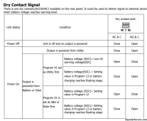
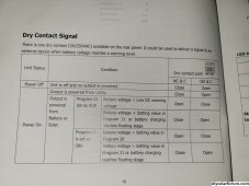
I'd like to use the dry contact signal (DCS) on the EG4 6000 to signal a solid state relay that will divert the pv input from the batteries to the heater once the batteries are full. Sounds simple enough right! Haha...wrong! ?
I understand the DCS produces no voltage, it's really just a switch but it's rated to 3A/250VAC.
I have program 1 set to SBU (Solar/Battery/Utility).
I have program 14 set to USE (user-defined)
Bulk Charge (17) 56.0V
Float Charge (18) 54.0V
Low DC cut-off (19) 48.0V
20230924_131951.jpg

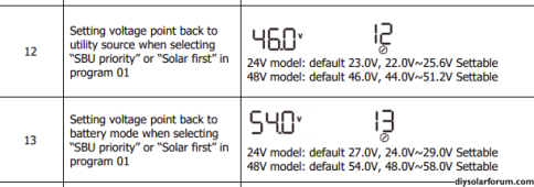
Program 20 is at default 46.0V (Can go as high as 51V)
Program 21 is at 54.0 V (Same as Float Charge)

So my understanding is that once the SSR is connected to the NC & C terminals, the DCS will trigger the SSR when the battery voltage goes above 54.0V. So far so good...i think. Ok so now how does it turn off? It surely can't wait until the batteries have discharged below Program 20: 46V, or even 51V! That seems way too low. Or does it turn it off when it drops below 54.1V? Seems like the heater will constantly be turning off and on if the only variable is 0.1V. Ok that's me stumped #1.

#2 is how to wire the SSR.
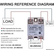
Screenshot_20230924_134532_Messages.jpg

This is my SSR and the wiring diagram. My guess is it gets power from the main panel to the input (live wire to terminal #3 and neutral wire to terminal #4) using 14/2 wire at 120VAC. Live wire then goes from terminal #1 (output) to the heater and that leaves terminal #2 (output). Do you connect a live wire to the C terminal of the DCS and the Neutral wire from the load to the NC terminal of the DCS?

If you might have any info on either of these, oh man would I ever appreciate some insight from anyone who knows what they're doing. I'm learning as I go and I'm equally ecstatic when I figure something out and pull-my-hair-out frustrated when I can't. What a rollercoaster!
Thanks in advance,
Your friendly Canadian amusement park enthusiast
 
actually running a micro-hydro system and have up to 500 continuous watts
Jealous!!
equally ecstatic when I figure something out and pull-my-hair-out frustrated when I can't
buy a ‘battery charge controller board’ and set it for your desired full vs disconnect voltage. I have one for nominal 12V but don’t know about nominal 48V items, though.

Anyway, these devices are generally rated on the output side at something modest like 10A at 120VAC, so you can either use a <10A “fan-heater” or use it to trigger an appropriately-rated relay. I’d probably trust a relay a lot more than a $10 controller board…

With an appropriate electric resistance heater of modest watts you can probably harvest a bit of that surplus.
Reality? Don’t spend a ton of money on the project. If you do the btu calculations on, say, 500W or even 1000W of electric heat the actual output is not as exciting as one might hope. It wasn’t for me, but I can do ~375W on sunny winter days for a few hours and since the only thing I had to buy was the $10 controller board it was “worth it.”

The problem I had was a bit of cycling of the heater-fan due to the “top end” of battery charging sagging and recovering relatively fast; you have so much overpanelling by the sounds that you may not see that- unless your heat is 3000W or whatever. If you lowered the low-V disconnect point so it ‘ate’ a bit of battery bank the battery bank would modulate that with a more stable voltage.
 
Thanks so much for your response!
Yes, a 500w heater doesn't sound like much but my cabin is only 12x14 and well insulated so it really doesn't need too much to keep the place comfortable. I'm mostly hoping that it'll just keep the pipes from freezing when I leave for a day or two so I don't have to continuously drain the cabin everytime I go!
Thanks for the recommendation of the controller board, I'll definitely look into it. Although it's a bit confusing that you say a relay will be more trustworthy and I already have a relay, I just don't quite understand how to set it up.
Anyway I appreciate your time, thanks and have a great day!
 
it's a bit confusing that you say a relay will be more trustworthy and I already have a relay, I just don't quite understand how to set it up
The board I bought was <$10.
Using a brand name heating system or other system relay that can endure the cycles and amps would give me comfort and confidence, while trusting the $10 board with much of a load does not.

I suggested the board because it eliminates the typical conservation and use functionality of your aio. For these devices most of which are not designed to utilize “surplus” in any fashion there isn’t usually any surplus-harvesting logic in the programming. The board sidesteps the barrier of the aio enabling you to borrow the surplus without eating much battery, but still harvesting ‘surplus ‘.
 
I'm looking for a similar logic for my AOI Inverter.

I have excess solar in my RV, and would like to run the 120V Resistive heater in my Water heater to reduce my propane usage. Sometime in the afternoon the inverter starts throttling when the batteries are full. At that point I would love to just turn on my electric heater.

1696353780738.png
1696353820785.png

When I interpret that correctly, when we configure for SBU mode - you can essential set 51.2V as the highest limit when the switch turns to Close and then whatever above to open again.

Which is not good since 51.2V is pretty far discharged....
 
set 51.2V as the highest limit when the switch turns to Close and then whatever above to open again
Whatever the voltage… they have to have some offset to keep the relay/contactor from going fluttery on/off
 
Whatever the voltage… they have to have some offset to keep the relay/contactor from going fluttery on/off
there are lots of ways achieving a hysteresis even when the input is fluttery.

I've used time delay relays - just set them to a minute or whatever. They will then only turn of if the signal is stable for at least on minute ON.
Also called ON-Delay Timer. Or if you want to lock out for a while after last actuation - OFF-Delay timer. Very simple devices.

But the logic to actuate is more difficult since LFP batteries have a very flat voltage curve. So would be great to get a signal either from the BMS or from the Charge controller.

Like when it's switching from Bulk to float.
 
Hello!

I appreciate everyone’s responses here. I’m new to the process so it all helps even though I don’t understand much of it.

@Ithoughtitwouldbeeasy - I believe I have a very similar setup to you with a micro hydro power supply (in the winter) and the EG4 6000ex invertor controller.

First up is the setup you described at the outset working?

2nd how are you connecting your turbine into the system?

Thanks!
 
I use a charge controller designed for hydro/wind that handles my resistive load. One reason why I dislike AIO setups is that I prefer having flexibility.
 
Hello!

I appreciate everyone’s responses here. I’m new to the process so it all helps even though I don’t understand much of it.

@Ithoughtitwouldbeeasy - I believe I have a very similar setup to you with a micro hydro power supply (in the winter) and the EG4 6000ex invertor controller.

First up is the setup you described at the outset working?

2nd how are you connecting your turbine into the system?

Thanks!
Hey! Haha I'm right with you. Everything is very helpful while simultaneously adding layers of confusion! I still haven't figured out exactly what to do.
No, nothing is working perfectly. I have 3 wires (AC power) coming out of my turbine and attached them to a 10/3 wire (720ft/210m run) that goes through a rectifier (converts to DC power) and then into the pv input of the eg 6000ex. I've had a maximum of 500 watts and a minimum of 160 watts depending on whatever the inverter feels like that day. My batteries stay anywhere between 50% and 70% charged even when I turn off all AC output power meaning that all of the incoming wattage should be charging the batteries. The only consistency is that the inverter never charged the batteries to 100%.
I'm thinking about selling this very complicated system and going with a much simpler midnite solar classic approach which has a seperate inverter and charge controller, and has a diversion load setup built into the charge controller....
 
Sorry to hear you’re not getting to full charge from your system.

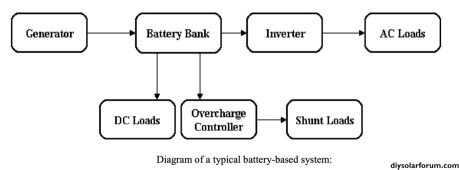
One of the turbine manufacturers I’ve been looking (energy systems design) at suggests this setup (where generator is the hydro turbine. I hadn’t realized it could work to attach the turbine directly to the battery instead of a charge controller. Wondering if the dry contact on the 6000xp can be used to trigger the overcharge controller?1699393574358.png
 
Sorry to hear you’re not getting to full charge from your system.

One of the turbine manufacturers I’ve been looking (energy systems design) at suggests this setup (where generator is the hydro turbine. I hadn’t realized it could work to attach the turbine directly to the battery instead of a charge controller. Wondering if the dry contact on the 6000xp can be used to trigger the overcharge controller?View attachment 176606
I'm picking up what you're putting down. I will have to see if this way of wiring everything would be compatible with my system....thanks!
 
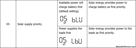
So I just finished another round of banging my head against the wall and managed to surface something! There is a setting in the program (#05) that prioritizes the PV input. BLU - Batteries, Load, then Utility or LBU - Load, Batteries, then Utility. Do you think it's possible, hear me out, to set the load as the priority (LBU)? I can hook up a 500W heater to a thermostat that will turn the heater on and off at certain temps. When it's on, the hydro input goes straight to the heater, and when the heater shuts off, the input goes back to the batteries. Because there is nothing draining the batteries (while I'm not home), even if the heater is on for like 6 hours straight during a cold night, the batteries shouldn't deplete. This may not be a permanent, maintenance free solution, but will it work while I'm away at work during the winter???
The only issue I can think of is if the inverter needs ~130W to run and the heater needs ~500W, will it work if my maximum PV input is only say 450W? Maybe the heater will just use whatever it can - just won't run as hot? Will the inverter draw from the batteries if the PV input isn't sufficient? I feel like being hopeful...Screen Shot 2023-11-07 at 17.56.29.png
 
Back
Top