diy solar

diy solar

using LV6548 dry contacts and a relay for dump load

khaledme

New Member
Joined
Sep 9, 2023
Messages
36
Location
USA
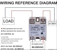
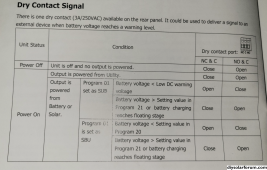
Does anyone knows how the dry contact works on LV6548 or 6500EX. The manual says that it is 250VAC 3A. I dont know what this means, is this 250VAC supplied voltage by the dry contacts or do I need to supply the voltage to it from another source, for example the inverter output?

Can I run a relay of these contacts to energize a dump load when batteries are full?
 
You could use it but you don’t have any control of the start voltage or stop voltage other than those that you may not want to mess with in your inverter settings. Those “dry contacts” have no voltage on them. You can use up to 3 amps and 250 AC from YOUR device you want to control. You may wish to use a contact in conjunction with another controller and/or timer. This works pretty well, lots of sellers on eBay and Amazon, pick the best reviews :
IMG_1047.png
 
Thanks for the idea about the voltage detector.
I was going to either use the power supply from the battery ( 48V ) or the inverter output 120V with C and NC contacts to trigger a power relay. S here is what either would look like. I have seen online somone uses DC signal input for the dry contact.

1697518263442.png
 
I went to measure the voltage between the dry contact C and NC and it is measuring voltage, I thought it should not any voltage
 
Thanks for the idea about the voltage detector.
I was going to either use the power supply from the battery ( 48V ) or the inverter output 120V with C and NC contacts to trigger a power relay. S here is what either would look like. I have seen online somone uses DC signal input for the dry contact.

View attachment 172654
I have been after exactly the same thing. I have a AC/AC SSR (photo attached) and came up with something similar: 20231110_150219.jpg The biggest red flag to me is the setting for program 21. The max voltage you can put there is 51V. This means that once the NC/C signals are closed (say at 54V with Program 20) and you have your diversion load running, they wont open again and send power back to the battery bank until the batteries hit 51V (roughly 16%) which seems way too low! Not sure how much sense that makes to you but I haven't figured anything else out yet...
 

Attachments

  • Screen Shot 2023-11-07 at 19.55.19.png
    Screen Shot 2023-11-07 at 19.55.19.png
    412 KB · Views: 13
  • Screen Shot 2023-11-09 at 15.03.02.png
    Screen Shot 2023-11-09 at 15.03.02.png
    2.5 MB · Views: 13
I have been after exactly the same thing. I have a AC/AC SSR (photo attached) and came up with something similar: View attachment 177060 The biggest red flag to me is the setting for program 21. The max voltage you can put there is 51V. This means that once the NC/C signals are closed (say at 54V with Program 20) and you have your diversion load running, they wont open again and send power back to the battery bank until the batteries hit 51V (roughly 16%) which seems way too low! Not sure how much sense that makes to you but I haven't figured anything else out yet...

I came to the conclusion that using the voltage detector would be a better option than using the dry contacts, that way I have better control on when the dump load is triggered.
 
I came to the conclusion that using the voltage detector would be a better option than using the dry contacts, that way I have better control on when the dump load is triggered.
have you found a solution?

I'm looking at the same usecase - I want to trigger my low watt waterheater element when my batteries are getting close to full.
 
have you found a solution?

I'm looking at the same usecase - I want to trigger my low watt waterheater element when my batteries are getting close to full.
My plan is to use voltage detector like this, set it up to trigger the NO contacts when the batteries are full, then will connect these contacts to a mechanical power replay AZ2280 to provide power to the water heater.

This setup is better than using the generator dry contacts in the inverter.
 

Attachments

  • 1702828776577.png
    1702828776577.png
    288.5 KB · Views: 4
How big of a load do you want to switch? Those DC sensing modules have 20A switching on 230V.

I don't want to have the dump load too big that voltage sags so far that it shuts off right away.

Do you have a two or one element water heater? I'm thinking replacing the lower one with a 500-1500W or so and a higher temperature setting then the upper element.

That would keep the lower one heating when battery is getting full and you still have the upper part of the water hot in case the batteries don't get full that day.
My system is not installed yet, so I have not gone that far in the calculations to see how much extra power I will have from the panels. I think you can control this by programming the voltage detector to turn on for a certain hours of the day. there are some videos on YouTube about how to do that. Or a smaller water heater element. I will get to this once I install the system and see how much extra PV power is available.
 
How big of a load do you want to switch? Those DC sensing modules have 20A switching on 230V.

I don't want to have the dump load too big that voltage sags so far that it shuts off right away.

Do you have a two or one element water heater? I'm thinking replacing the lower one with a 500-1500W or so and a higher temperature setting then the upper element.

That would keep the lower one heating when battery is getting full and you still have the upper part of the water hot in case the batteries don't get full that day.
to answer the question about the load, I am not planning on running the load through the voltage detector, that is why I am using a Power relay so the load is running through it and not running through the voltage detector
 
Here is a schematic of what it would look like with the voltage regulator and power relay.
I also found the manual for the voltage detector online.

1702842788110.png
 

Attachments

  • digital-relay-E1200.pdf
    414.9 KB · Views: 1
Back
Top