diy solar

diy solar

EG4 18Kpv Dump Load

Steve777

New Member
Joined
Oct 23, 2020
Messages
123
Been looking at possible replacement inverters, and the EG4 18Kpv seems like a pretty good match for my needs. One "feature" which I had hoped to implement in my system was adding a dump load (hot water heater element) to make use of extra power when the batts are close to fully charged. From looking at the 18Kpv manual, the inverter has a set of NO/NC relay contacts (the "DRY contacts") separate from the generator contacts, but there is nothing in the manual on how to use/program that relay.

Does anyone know if it is possible to control this DRY contact relay based upon battery SOC or voltage? How about setting separate on and off voltage levels so one can build in some hysteresis?

Thanks
 
Why would you want to do this? The inverter itself is capable of shutting off input energy of all types when your batteries are full...
 
Been looking at possible replacement inverters, and the EG4 18Kpv seems like a pretty good match for my needs. One "feature" which I had hoped to implement in my system was adding a dump load (hot water heater element) to make use of extra power when the batts are close to fully charged. From looking at the 18Kpv manual, the inverter has a set of NO/NC relay contacts (the "DRY contacts") separate from the generator contacts, but there is nothing in the manual on how to use/program that relay.

Does anyone know if it is possible to control this DRY contact relay based upon battery SOC or voltage? How about setting separate on and off voltage levels so one can build in some hysteresis?

Thanks

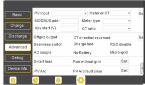
Search in the 18kpv manual for a feature called 'Smart Load'.. You can change the Gen input port into an aux (luxury loads) output where it can supply power output under certain triggers (like a certain SoC trigger-point for example)...

You can still plug a generator into the normal AC input, and use an ATS if using Smart Load feature...


Ref:


"Smart Load:
This function will make the GEN input connection point to a load connection point. If enabled, the inverter will supply power to this load when the battery SOC and PV power are above user set values.

For Example:
Smart load start SOC=90%
Smart load end SOC=85%
Start PV power=1kW
means:
When the PV power exceeds 1000W, and the battery system SOC gets to 90%, the Smart Load Port (GEN) will automatically switch on to power the connected load.

When the battery reaches SOC<85% or PV power<1000W, the Smart Load Port automatically switches off.

Important Note:
If the smart load function is enabled, agenerator cannot be connected at thesame time; otherwise, the device will bedamaged!"
 
Last edited:
@Shinzul - the reason to do this is just to make use of that extra energy which otherwise would go to waste.

@Samsonite801 - I am aware of the "Smart Load" feature, and that would do pretty much what I want. Except it takes over the generator input. I am looking to implement that smart load functionality without using the generator input as an output, as I plan to have a generator connected there. I am fine with adding a high current relay/actuator to do the switching of the load, just need a way to control it.

Would be nice if the dry relay was controlled by the Smart Load logic without forcing the gen input to become an AC out. Seems that most of the logic and user i/f is already there for that, just need an additional switch for whether to power the smart load to the gen input or just have it run the dry contact relay.

Yeah understood. So one option (if you can't find a way to use the dry contact relay instead), is to just add an auto (contactor-based) ATS to switch the AC line to generator upstream.

But perhaps you can figure it out.

One other thing I might say here though. In my experience tinkering with the 18kpv, is that the EG4 manual is incomplete. When searching for info for this inverter, don't forget to look also in the LuxPower Tek 12k manual as well, and also Google for LuxPower Tek 12k when looking for info, because they've been on the market in that trim for much longer, so the info and experiences from other users is more complete to include in your searching.

I found way more settings detail and screenshots in the LuxPower Tek manual though, when I had been searching (when working with a neighbor's 18kpv).

Also, don't forget to post back here if you figure out anything else regarding custom setup of the dry contacts...
 
Last edited:
If you have two (or more) 18Ks in a parallel configuration, can you configure them for genny on one (some) 18Ks and Smart Load on (the)other(s)?

Also: can you have different smart load setpoints on different 18Ks in a parallel configuration (with the smart load/genny ports not tied together, of course).
 
Search in the 18kpv manual for a feature called 'Smart Load'.. You can change the Gen input port into an aux (luxury loads) output where it can supply power output under certain triggers (like a certain SoC trigger-point for example)...

You can still plug a generator into the normal AC input, and use an ATS if using Smart Load feature...


Ref:


"Smart Load:
This function will make the GEN input connection point to a load connection point. If enabled, the inverter will supply power to this load when the battery SOC and PV power are above user set values.

For Example:
Smart load start SOC=90%
Smart load end SOC=85%
Start PV power=1kW
means:
When the PV power exceeds 1000W, and the battery system SOC gets to 90%, the Smart Load Port (GEN) will automatically switch on to power the connected load.

When the battery reaches SOC<85% or PV power<1000W, the Smart Load Port automatically switches off.

Important Note:
If the smart load function is enabled, agenerator cannot be connected at thesame time; otherwise, the device will bedamaged!"

I think you'd be better off just designing it with some relays. That's what I did for my EV charger. I have other relays I could trip, but the EV daemon was trivial with the openevse box. Also too many parameters get confusing, I'd just find a threshold and run with it. Lastly driving a HWH this way is not productive unless you use a lot of hot water. EV is great because the load is predictable while it is on.

I use a sliding Target SOC based on TOD, and signal the evse to adjust it's rate, allowing it to ramp up if it's 3% over the desired SOC, and ramp down if below desired SOC. I do this to bleed battery assuming it will charge it back the next day when I have the car at work.

1]20240116-225801 1650798 Status/Pilot/Rate: disabled / 40 / 0 SOC/Target: 69 / 67
1]20240116-225801 1650798 - Sleep(119)
1]20240116-230000 1650798 Status/Pilot/Rate: disabled / 40 / 0 SOC/Target: 69 / 66
1]20240116-230000 1650798 Charging Limit set to 6
1]20240116-230000 1650798 -- UPDATED: EVSE rate updated -> 6
1]20240116-230000 1650798 - Sleep(120)
1]20240116-230200 1650798 Status/Pilot/Rate: active / 6 / 6 SOC/Target: 69 / 66
1]20240116-230200 1650798 -- UPDATED: EVSE rate updated -> 7
1]20240116-230200 1650798 - Sleep(120)
. . .
1]20240117-012800 1650798 Status/Pilot/Rate: active / 12 / 12 SOC/Target: 58 / 58
1]20240117-012800 1650798 - Sleep(120)
1]20240117-013000 1650798 Status/Pilot/Rate: active / 12 / 12 SOC/Target: 57 / 58
1]20240117-013001 1650798 -- UPDATED: EVSE rate updated -> 8
1]20240117-013001 1650798 - Sleep(119)
. . .
1]20240117-014400 1650798 Status/Pilot/Rate: active / 8 / 8 SOC/Target: 56 / 57
1]20240117-014400 1650798 -- UPDATED: EVSE rate updated -> 0
1]20240117-014400 1650798 Charging Disabled
. . .

Solar Assistant or something can probably get you the data you need to make the decisions. The inverter interface and software is just not that great for bending it to do odds and ends, you might get something to work, but every time you look at it you are going to go: Now what did I do again? Worse case you can do what I did. I poll the modbus port on the inverter every 30 seconds and record it in a postgres database, on an OrangePi5.

Even harder to predict the sun sometimes.
 
I think you'd be better off just designing it with some relays. That's what I did for my EV charger. I have other relays I could trip, but the EV daemon was trivial with the openevse box. Also too many parameters get confusing, I'd just find a threshold and run with it. Lastly driving a HWH this way is not productive unless you use a lot of hot water. EV is great because the load is predictable while it is on.

I use a sliding Target SOC based on TOD, and signal the evse to adjust it's rate, allowing it to ramp up if it's 3% over the desired SOC, and ramp down if below desired SOC. I do this to bleed battery assuming it will charge it back the next day when I have the car at work.

1]20240116-225801 1650798 Status/Pilot/Rate: disabled / 40 / 0 SOC/Target: 69 / 67
1]20240116-225801 1650798 - Sleep(119)
1]20240116-230000 1650798 Status/Pilot/Rate: disabled / 40 / 0 SOC/Target: 69 / 66
1]20240116-230000 1650798 Charging Limit set to 6
1]20240116-230000 1650798 -- UPDATED: EVSE rate updated -> 6
1]20240116-230000 1650798 - Sleep(120)
1]20240116-230200 1650798 Status/Pilot/Rate: active / 6 / 6 SOC/Target: 69 / 66
1]20240116-230200 1650798 -- UPDATED: EVSE rate updated -> 7
1]20240116-230200 1650798 - Sleep(120)
. . .
1]20240117-012800 1650798 Status/Pilot/Rate: active / 12 / 12 SOC/Target: 58 / 58
1]20240117-012800 1650798 - Sleep(120)
1]20240117-013000 1650798 Status/Pilot/Rate: active / 12 / 12 SOC/Target: 57 / 58
1]20240117-013001 1650798 -- UPDATED: EVSE rate updated -> 8
1]20240117-013001 1650798 - Sleep(119)
. . .
1]20240117-014400 1650798 Status/Pilot/Rate: active / 8 / 8 SOC/Target: 56 / 57
1]20240117-014400 1650798 -- UPDATED: EVSE rate updated -> 0
1]20240117-014400 1650798 Charging Disabled
. . .


Solar Assistant or something can probably get you the data you need to make the decisions. The inverter interface and software is just not that great for bending it to do odds and ends, you might get something to work, but every time you look at it you are going to go: Now what did I do again? Worse case you can do what I did. I poll the modbus port on the inverter every 30 seconds and record it in a postgres database, on an OrangePi5.

Even harder to predict the sun sometimes.


Yeah that's an awesome way to do it too, you have that Openevse on an RPi hardware or something else?

I have a Victron BMV-712 which has a relay in it, although I'm using it for a heater right now, it can also control the relay based on SoC as well.
 
Yeah that's an awesome way to do it too, you have that Openevse on an RPi hardware or something else?

I have a Victron BMV-712 which has a relay in it, although I'm using it for a heater right now, it can also control the relay based on SoC as well.
The openevse box is just on Wifi, I bang the API from an OrangePi5, that also polls the inverters with modbus, all custom for fun.
 
Openevse is Wifi/API. 18KPV is modbus RS-485. Docs are online, though modbus is somewhat arcane. The EG4 sends it's serial number back with every reply, and you have to poll them independently, though they can share the bus as long as you change the ID's. I wrote all that code in 'C' because I like doing things the hard way. (OK, because I don't like python).
 
Openevse is Wifi/API. 18KPV is modbus RS-485. Docs are online, though modbus is somewhat arcane. The EG4 sends it's serial number back with every reply, and you have to poll them independently, though they can share the bus as long as you change the ID's. I wrote all that code in 'C' because I like doing things the hard way. (OK, because I don't like python).
So what hardware interface do you use for the 18Kpv? Can you talk modbus over the LAN or do you use the RS485 serial interface? It’s not clear if I can connect the 18Kpv and the Wallmount batteries in closed-loop mode and still talk Modbus to the 18Kpv
 
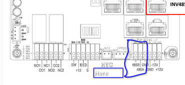
RS-485. There are multiple ports. I was running two wire so I used these :

1708819625001.png

You need to set the ID's for the port. It's buried in the LCD menu somewhere, mine are on 6 & 7
 
If you have two (or more) 18Ks in a parallel configuration, can you configure them for genny on one (some) 18Ks and Smart Load on (the)other(s)?

Also: can you have different smart load setpoints on different 18Ks in a parallel configuration (with the smart load/genny ports not tied together, of course).
This is my question exactly. Interested in getting two 18Ks and using one as my auto-start backup generator on one 18K and have Smart Load output on the other 18K.

Would love to see this get answered by someone doing it!
 
Back
Top