diy solar

diy solar

Simple campervan solar setup: need some assistance reg. max current from alternator.

tripcode

New Member
Joined
Jul 20, 2020
Messages
12
Hi, this is my first post and likewise, my first solar DIY build :) I am using this guide as my baseline: https://www.mobile-solarpower.com/simplified-400-watt-fewer-wires-and-alternator-charging.html .

I am currently traveling Australia and just recently purchased a campervan that I am in the process of equipping with the products listed below, based on these calculations:
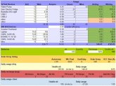
tmp.JPG

My solar array:
- 2x250W Mono Solar Panels, rated at 12V / 18.6V (max) and open circuit 22.5V. (https://www.ebay.com.au/itm/12V-250...e=STRK:MEBIDX:IT&_trksid=p2057872.m2749.l2649)
- Renogy DC DC Dual Battery charger with an integrated MPPT 50A max current and 25V max voltage ( https://www.ebay.com.au/itm/Renogy-...e=STRK:MEBIDX:IT&_trksid=p2057872.m2749.l2649)
- 2x10⁵ Ah deep cycle batts
- 1000W inverter
- Misc, such as fuses and fuseboxes.

Here are the areas, where I need help:

1. Given the fact that my Renogy SCC is rated at 50A max, with 25V max input, I cannot wire my panels in series, correct? Because, 22.5V x2 > 25V.

2. This leaves me with the option of only running the setup in parallel, which looks like this: 500W/18.6V = 26,88A. Now with optimal charging conditions, i.e. on a super sunny day, I would waste 1.88 A if I am driving around. Because during dual-battery-charge-mode the Renogy will split the max current to 25A/25A. Is this correct...? I mean, since it is only 1.88 A I think its not too bad. But question here is, shouldnt the SCC always be sized to have a little extra room, i.e. my setup will most likely run on its 'maximum potential' a lot from what it seems.. will this do any 'harm'?

3. Pretty much a follow up question to 2., what happens to the excess 1.88A ...I assume it will just not be 'drawn' by the Renogy module and thus it sits in the form of 'unused energy' on the solar panels? This will not cause any troubles I assume.

4. I double checked with my mechanic, my cars alternator is rated at 90A. Thinking again about this 25/25A mode that I am facing when driving around. Isnt it a big waste to have all the Amps from my alternator 'throttled' at 25A? I could help this situation out a bit, by installing a circuit breaker on the solar panels positive I suppose and switching it off manually, if I am driving around on a cloudy day to avoid a situation where I would get 25A from the alternator and 5A from PV. Thus, allowing me a 50A max from the alternator, however.. its still nowhere near what my alternator can output maximum, which is 90A! Did I just make a big mistake by deciding for the Renogy Dual Battery Charger?

5. My understanding, when going a bit more in-depth with question 4, is that the Alternator will charge my starter batt, once that reaches a certain voltage threshold, the Renogy adapter will relay the Alternator current to my house batts. Or auxillary batts. Now, am I too optimistic by thinking the alternator would actually output 90A ... ? Is the output frmo the alternator in reality much lower, because it is still tied up to the starter batt, regardless if it is full or not?

6. What are the weak-points/flaws in this setup besides the topics I have addressed in my questions above?

7. Assuming I am right and 4. and 5. seem to be bottlenecks: Would it help if I had a SCC dedicated for my solar setup and use an isolated VSR that is rated to handle 90A to charge my house batts. I.e. send my Renogy module back and do everything seperately by using a dedicated MPPT and VSR?
 
1. Correct. parallel only.
2. I don't follow you at all on this. I think you're getting input current confused with output current. They're different and not directly related.
3. Nothing. You're imagining an issue that doesn't exist.
4. Why would your alternator be "throttled at 25A"?


5.
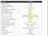
1595305852119.png

1595306305436.png
Your alternator has max voltage and current. It will only push as much current as it can until the battery hits bulk voltage, and then it will taper the current to maintain the bulk(absorption) voltage.

6. Dunno.
7. You're not. They aren't. No.

Lastly, more current isn't better. A 100Ah FLA/AGM battery is happiest when charged at 0.1C or 10A for a 100Ah battery (LFP can go much higher). Higher charge currents can damage them. You can often go as high as 20%, so if you have 2X 100Ah batteries in parallel, 40A is probably fine. Again, if you have LFP batteries, these current limits don't apply.
 
1. Correct. parallel only.
2. I don't follow you at all on this. I think you're getting input current confused with output current. They're different and not directly related.
3. Nothing. You're imagining an issue that doesn't exist.
4. Why would your alternator be "throttled at 25A"?


5.
View attachment 18034

View attachment 18035
Your alternator has max voltage and current. It will only push as much current as it can until the battery hits bulk voltage, and then it will taper the current to maintain the bulk(absorption) voltage.

6. Dunno.
7. You're not. They aren't. No.

Lastly, more current isn't better. A 100Ah FLA/AGM battery is happiest when charged at 0.1C or 10A for a 100Ah battery (LFP can go much higher). Higher charge currents can damage them. You can often go as high as 20%, so if you have 2X 100Ah batteries in parallel, 40A is probably fine. Again, if you have LFP batteries, these current limits don't apply.

Hey! Thanks a lot for the reply, especially the bottom bit of your response was helpful, with respect to the charging current. You are absolutely right, in an ideal world we want to keep the batts happy and charge them slow and steady and not bombard them with a tremendous amount of amps. So therefore, the 50A limitation seems very legit on my Renogy charger.

Regarding question 2., let me elaborate a bit. In the Renogy manual.pdf (thanks for linking btw) you can see on page 15, point 3.3 the behaviour of the charging logic, when the solar panels cant keep the house batteries on a constant voltage charge. I.e. if there is too little power from the solar panels. E.g. on a cloudy day while driving around.

So lets assume, the PV charge results in roughly 5A, thus..the renogy charger will kick in the alternator as a secondary charging source, for my house batteries. Now there is a 'hard-wired' limitation of 25A per source of charge, which is the alternator and the solar panels. But in this scenario it would even make sense to use 50A from the alternator and ignore the 5A from the solar completely. I mean ideally, it would consume 45A from the alternator and the remainder from the 5A. But this is not supported as far as I understood. Thus, the only way to achieve this desired result would be to break the circuit for the solar panels, so the renogy will read no input voltage for PV and in return charge with 50A from the alternator.

Does this make sense?

Also 3. is pretty much irrelevant, was just out of curiosity... as in: what happens to the energy/or potential energy from the solar panels, that is not being used.. it just sits 'in the panels' in form of 'heat'?

4. Only in special situations, where my solar array is not able to produce enough current to keep the house batts in a constant voltage charge, the renogy will cut in the alternator - running in a 'dual' mode. where both sources will be rated at 25A max. Which is fine, with some exceptions ...see my comment to 2. above.


New question that just popped up in my head: Do I wire the DCDC charger to the starter batt or to the alternator directly, I think both options are viable. Is there a big difference? I suppose if wired to the alternator directly I will have the starter battery isolated from my house battery system? Whereas going to the starter battery, will have it integrated in the house battery system, but only if the VSR readings are right. I.e. the starter battery is on 13V+ (I think).

Last but not least, by following this diagram: https://www.mobile-solarpower.com/uploads/1/2/9/6/12964626/122-fgood_2_orig.jpg I should be fine, right? I think my setup will look more or less the same.
 
2. It's designed to favor solar because that's "free". Again, more current isn't better. Yes, cutting the panels via a breaker should enable UP TO 50A from the alternator, but again, this is a bad idea unless you have the battery for it. What's more important? Getting an extra 20A of charging or getting an additional year or two out of your battery? It's also likely that you're mostly going to be demanding "float" voltage from the service battery, which means the need from the alternator will be very low... perhaps as little as half an amp.

3. MPPT are basically fancy DC-DC converters. They just don't use the excess power coming in from the panel if they can't use it. They can essentially go open circuit to the panel if necessary. Panels only produce power if the circuit is closed. if your panel is disconnected there is no current flow. The MPPT charge controller simply pulls the current it needs and no more.

4. Alternator isn't throttled. Alternator will put out UP TO 25A to the charger if that's what it demands, but it will put out whatever it wants up to its maximum based on need (charging chassis battery and running vehicle systems).

I would wire it according to p. 13. That diagram looks correct.
 
Another factor is you don’t necessarily want to draw too much power from your alternator. It doesn’t seem to be a problem for lead acid batteries as much as lithium because LA has a higher internal resistance so doesn’t draw as much charge.

I’ve been looking for guidelines on how much power is ‘safe’ to draw from an alternator to reduce the risk of damaging it (the risk seems to be mainly at idle speeds because the alternator gets to hot due to reduced airflow from its internal fan)

I haven’t got specific evidence as yet but I think normal vehicle alternator loads should be 33% engine/starter battery and 33% max charging with the other 33% headroom. This is not tested and I haven’t got any real evidence it’s just gleaned from lots of titbits I’ve picked up looking into it.

The story changes of course when vehicle engine systems are designed with specific components for battery charging. I believe this is often the case in ambulances and also many yacht engines.
 
2. It's designed to favor solar because that's "free". Again, more current isn't better. Yes, cutting the panels via a breaker should enable UP TO 50A from the alternator, but again, this is a bad idea unless you have the battery for it. What's more important? Getting an extra 20A of charging or getting an additional year or two out of your battery? It's also likely that you're mostly going to be demanding "float" voltage from the service battery, which means the need from the alternator will be very low... perhaps as little as half an amp.

3. MPPT are basically fancy DC-DC converters. They just don't use the excess power coming in from the panel if they can't use it. They can essentially go open circuit to the panel if necessary. Panels only produce power if the circuit is closed. if your panel is disconnected there is no current flow. The MPPT charge controller simply pulls the current it needs and no more.

4. Alternator isn't throttled. Alternator will put out UP TO 25A to the charger if that's what it demands, but it will put out whatever it wants up to its maximum based on need (charging chassis battery and running vehicle systems).

I would wire it according to p. 13. That diagram looks correct.

Cheers. I think I have a clearer picture of this setup now, after reading 4. it makes more sense. I.e. the alternator puts up to 90A out. IF NEEDED. So it can supply the starter batt, the cars power consumption in general, radio etc. but if you have been driving around for a while and batt is full, the alternator wont be much needed. I.e. you probably only rarely run into situations where the alternator outputs the full 90A ..at least in old vehicles. Unlesse there are a lot of electrical accessories in your car that are draining the car battery. And assuming you dont have house batteries of course, but anyway this was off-topic.

Just to recap:
The 50A limitation is ok, as we dont want to draw much more current for this setup either way. Even if the alternator gets cut into the charging circuit of the Renogy DCDC charger, i.e. PV 25A + Alt 25A, this is just the max current it would potentially draw. The charging module will always try to get its power from the PV source first, as it is considered 'free' energy.

Also according to some really quick googling, the MAX (less is better of course) charging current recommended for lead acid batts is 25% of its capacity, that would be around 25A , but since I have two 50A. Correct?
I think you're on the right track there.
If you look at Redarc's recommendation, the BCDC1240D is recommended for 200AH+ batteries.
I have dual 50AH LiFePO4 batteries in parallel with a BCDC1225D and a pair of nasty flexible no-name Chinesium panels on the roof that give me peak 55w, but that's not all day... So slightly oversizing your solar won't hurt you because it will only give you peak power for a short time each day. Whether you go series or parallel with the panels, it doesn't really matter (apart from cable sizing) because watts are watts. Give the charge controller the voltage that it can handle and it will handle the rest!
My controller has solar priority but will max out at 25A delivered to my batteries regardless of the input, which is perfect for my setup - that's .25C
I think your setup will be just fine.
Also - wire the controller to the starter battery, not the alternator and use a terminal fuse at the starter battery end. Car fires are no fun.

Didnt know redarc, is this a well known brand in AU? Sounds good though, thanks for the comment. I already run an auxillary battery that is wired to the starter batt using a VSR. I will just remove the VSR, replace it with my Renogy Charger and the rest should be easy, except of course for mounting the solar panels. I do have racks on the roof though, so that might help.

Last but not least, are you saying running the 250W solars in series would work? This is contradictory to what everyone else has been saying and it doesnt seem to add up with my calculations also, because the open circuit voltage is 22.5V x 2 = 45V, whereas my charger can handle a max input voltage of 25V! Also in the manual it reads that if the input voltage is too high, it will not charge. Wait X seconds and read the voltage again, to make sure it is in a safe zone.
Hi @tripcode - Yes Redarc is HUGE is in Australia (it's an Australian company, and most of their stuff is made in Australia) - top quality gear. Very popular in the 4WD/Touring communities, and is considered pretty much unbreakable. e.g. the DC-DC chargers are designed to be attached to chassis rails and are fully potted.

redarc.com.au

With regard to your panels, you'll have to go parallel because of the voltage. What I said was watts is watts (watts = volts x amps) so you'll still get the same number of watts regardless how you wire the panels, but you in this case are restricted by the max input voltage of the DC-DC charger (Redarc have the same limitation, that's why my panels are wired in parallel.). When going parallel, you will need to look at the voltage loss calculators to make sure that you have the right gauge wire between the panels and the charger (because of the higher current). Typically the MPPT chargers will run a renogy 100w compact panel at about 18v / 5.7A to get max power from it so use that figure in your voltage calculator. (for Parallel, same voltage, double the amps)


Hope this helps.
 
Back
Top