diy solar

diy solar

Smart shunt question

Chaucer

New Member
Joined
Oct 1, 2022
Messages
74
Hi,

Quick smart shunt question.

I have my system on shore power. When I turn on devices, the smart shunt shows an increase in power and amps. Even though it's not running on battery only, is that how it works (reconize the loads)? Just making sure I have things wired ok. I am certain it's on shore power because my 120 outlets work.

Thank you
 
The shunt should only show power into the battery or out of the battery if wired correctly
info on your equipment and wiring pics will help with your system troubleshooting if you can post them
 
Not necessarily related to your problem...

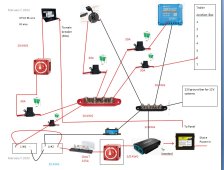
Both positive terminals should be connected to one side of the t-class fuse, and the other end of the fuse to the busbar. The way you have it setup, a short on the busbar side is not protected.

What is on the top left in the picture?
 
Not necessarily related to your problem...

Both positive terminals should be connected to one side of the t-class fuse, and the other end of the fuse to the busbar. The way you have it setup, a short on the busbar side is not protected.

What is on the top left in the picture?

Hi,

Do you mean both postive terminals of each battery? The Class T fuse is to protect the dedicated inverter circuit. Everything going to the pos. bus bar is 30 amps or less on 10 AWG wire only and is protected by a 30 A fuse in between the battery and bus bar (shown).

The top left is a WFCO power center with a converter/charger,
 
Hi,

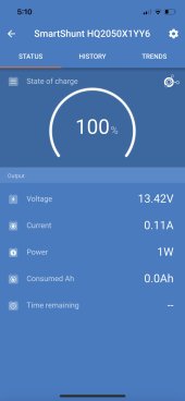
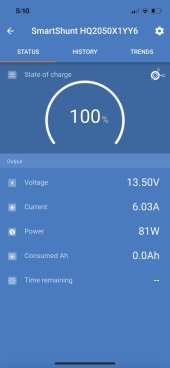
An update. I've realized that when the battery switch (red switch in diagram ) going to the WFCO is off, the smart shunt shunt shows almost no power draw (left below) , which makes sense , but when the battery switch is on, the smart shunt shows 6.03 A /81W and the fan for the convert/charger is on. So I guess it's the converter/charger working to charge the battery.

Battery switch off.jpg Battery switch on.jpg
 
Black wire from WFCO to busbar?
Hi, Not shown in diagram, but the 12 V black (actually white wires) go to the box shown on the right of the diagram listed as "12V ground bar for 12V systems" which is wired to the neg. bus bar and then to the shunt. So all the 12V loads go to the shunt via the ground bar shown on the diagram.
 
I put my Class T fuse as close to the battery as possible. The purpose of a Class T fuse is to protect the wire from a Full short circuit. It could go on negative or positive. It is also Okay to have redundant ones to protect the inverter of other devices for other overcurrent situations. A Full short circuit could draw a lot of Amps and fuse another lightweight fuse so that is why I put mine at the battery terminal. 12V is not as critical as 48 Volts and the current that could be released from my 42 kWh pack.
 
Hi, The Class T is only 6" from the battery. It's very close. Someone else on this forum told me that was acceptable.
 
Looks like the only path to the negative of the battery is through the shunt so you're good there. Question: Is your inverter powering your converter?
 
Looks like the only path to the negative of the battery is through the shunt so you're good there. Question: Is your inverter powering your converter?

No it's not. The converter/charger is wired in the transfer switch to a contact to only be powered when on shore power.

So the converter/charger will continue to run (with fan) because it can not get to the float votage for Li batteries? (It's a converter/charger for lead acid batteries, I have not upgraded that yet. .solar gets me to 100%)
 
Shouldn't current be positive or negative depending upon whether current is flowing into (charging) or out of the battery?
 
In your diagram, I see a Renogy 2000 watt inverter to the left of the transfer switch. Is that what you mean as a converter?
 
Back
Top