diy solar

diy solar

Smoke detection shutdown ciruit

brackstone

New Member
Joined
Mar 27, 2021
Messages
109
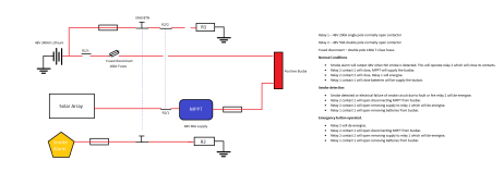
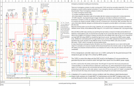
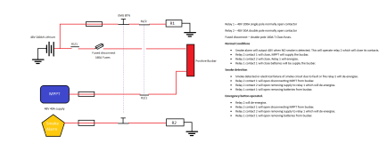
I am looking at designing and installing a smoke detection system in my solar cupboard which will shut down the system if either smoke is detected or an emergency button is operated. Attached is my circuit design and a description of the circuit.

I would love to know your thoughts on this before I start building it.

The smoke detector I will be building later incorporating an Arduino.

Smoke protection cicuit.png
 
A couple of thoughts:

Some charge controllers don't like having the battery disconnected while operating. It lets the smoke out! So if it falses or you test the e button, you might destroy the charge controller.

You don't need the arduino if this is its sole function. It could be done by just hacking the smoke alarm and using the open collector output which drives the alarm. That can pull in a relay (e button in series). The normally closed relay contacts would interrupt the the DC circuits.

If this system is big, R1/R2 are going to be big contactors!
 
It can be a simpler thing.
A standard smoke alarm triggers other smoke alarms with a 9v dc output. This can be used to control a relay that can do anything that you want it to.
 
A couple of thoughts:

Some charge controllers don't like having the battery disconnected while operating. It lets the smoke out! So if it falses or you test the e button, you might destroy the charge controller.

You don't need the arduino if this is its sole function. It could be done by just hacking the smoke alarm and using the open collector output which drives the alarm. That can pull in a relay (e button in series). The normally closed relay contacts would interrupt the the DC circuits.

If this system is big, R1/R2 are going to be big contactors!
Good point I should have looked at solar array disconnect first to the MPPT then the battery disconnect will have to think about this as the voltage would be much higher on this side for the contacts and a DC voltage might cause a good arc. I will look at a suitable contact for this.


R1 is a 200A contactor so should be OK disconnecting the batteries.

I was thinking of doing what you said from smoke alarm with a bit of modifying. I was also thinking running the output into a raspberry pi with server setup so an email alert can also be sent to me. The Pi or Arduino which ever used can give a 1 second delay between solar input shutdown and battery disconnect. It can also operate ventilation shutdown which is in the future.
 
BTW, Tim's point is good but you can still find cheapo smoke detectors that are not networked, even though that's required now, so you might not have the 9VDC output.

I harvest the americium buttons from smoke detectors and am always amazed that tou can still get the non-networked units. $3-4 each at HabitatForHumanity stores, flea markets, etc.
 
I have not looked into the somke detectors yet, I was thinking of using the siron output into the Pi which should be enought voltage so the Pi knows it has been triggered. I will look into the network ones if this does not work
 
This is a hard wired device which is good but does not have a aux output to trigger another device which is whay i thought you meant. I am sure the output from either the LED or the siron can be used to tell a Rasberry pi that the smoke has been detected and I could hard wire this off the inverter as it has internal backup battery
 
This is a hard wired device which is good but does not have a aux output to trigger another device which is whay i thought you meant. I am sure the output from either the LED or the siron can be used to tell a Rasberry pi that the smoke has been detected and I could hard wire this off the inverter as it has internal backup battery
It does have a 9v output when it is triggered.
I'm Actually using one to trigger auxiliary lighting.
 
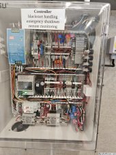
I've built a controller for monitoring and emergency shutdown. The emergency shutdown will occur in case of pushing either one of the two "emergency stop" buttons (one inside and one outside of the house) or one of 3 Kidde smoke detectors are triggered via Kidde SM120X Interconnect relay which are placed over the parallel AIO inverters or via remote controlled smart relay (the remote relays are integrated in my existing smart home system to be able to also shtudown the system by other type of rules/conditions, e.g. a camera may detect smoke over the inverters, etc.). The emergency shutdown circuit is build just with some relays (no microcontroller) and the monitoring is done via SolarAssistant with a Raspberry Pi. I put everything together in a DIN rail enclosure and also installed a fan with temperature controller for the DIN rail enclosure.


Some implementation details and points:

In my case, the EG4-6500EX AOI inverters, are only doing a real "cold" shutdown if all energy sources will be disconnected (this is what I want to achieve in case of emergency/fire).
  • battery
  • AC-in
  • PV
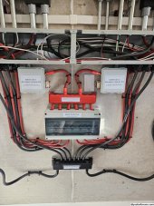
For battery disconnect of my two battery racks, I' using two 48V/600A golf cart contactors one for each battery rack.
For AC-in disconnect of my six EG4-6500EX inverters, I'm using two 120V/110A 3 pole contactors one for each phase.
For PV disconnect (Rapid Shutdown System) of my 40 PV panels, I'm using 20 of the Tigo TS4-A-2F remote switches with one RSS-Transmitter.

The PVRSS is by far the most costly part. But in some areas it's already a requirement to integrate a PVRSS in a PV system to protect the life of the first responders against high PV voltage. I live in Arizona and here a PVRSS is not yet a requirement, because the state still follows the "old" NEC2008 standard. But the current NEC2017 standard requires it already!
If you may find high voltage PV contactors you may also be able to make the PV disconnect simpler - but in this case it will not be NEC2017 compliant.

It took me a while to make the decision to go for the PVRSS (even it's not yet a requirement here - but soon) for the PV disconnect and spend this huge extra amount of money. But after considering things like permit, inspection, federal incentives, house fire insurance, resell value of the house, etc. I've decided to go with the complete PVRSS solution for PV disconnect part.

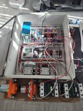
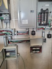
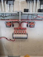
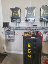
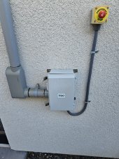
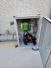
The left picture was the circuit while in building and testing phase. On the bottom left you can see the two 600A battery contactors and on the bottom right the two 3-pole AC-in contactors. The other pictures shows how they are mounted and placed on the wall.

20221221_140732.jpg20230314_103029.jpg20230314_103011.jpg

20230314_102959.jpg20230716_081453.jpg20230716_081500.jpg

The shutdown controller and monitoring circuit is now running for about 4 month without issues - after correcting some initial problems. Btw. The system is not yet finished. The Inverters, AC-in charger, batteries are working - but PV panels are not yet installed because of time constraints and heat in Arizona. But I've done some PVRSS tests with some of the panels just to check if this also works and it does. So far I've charged the batteries via grid and will be able to drive the whole house from batteries/inverters in case of grid failure - like an UPS.

This is the final schematic:
Screenshot_20230716_083242.png
 
Last edited:
I've built a controller for monitoring and emergency shutdown. The emergency shutdown will occur in case of pushing either one of the two "emergency stop" buttons (one inside and one outside of the house) or one of 3 Kidde smoke detectors are triggered via Kidde SM120X Interconnect relay which are placed over the parallel AIO inverters or via remote controlled smart relay (the remote relays are integrated in my existing smart home system to be able to also shtudown the system by other type of rules/conditions, e.g. a camera may detect smoke over the inverters, etc.). The emergency shutdown circuit is build just with some relays (no microcontroller) and the monitoring is done via SolarAssistant with a Raspberry Pi. I put everything together in a DIN rail enclosure and also installed a fan with temperature controller for the DIN rail enclosure.


Some implementation details and points:

In my case, the EG4-6500EX AOI inverters, are only doing a real "cold" shutdown if all energy sources will be disconnected (this is what I want to achieve in case of emergency/fire).
  • battery
  • AC-in
  • PV
For battery disconnect of my two battery racks, I' using two 48V/600A golf cart contactors one for each battery rack.
For AC-in disconnect of my six EG4-6500EX inverters, I'm using two 120V/110A 3 pole contactors one for each phase.
For PV disconnect (Rapid Shutdown System) of my 40 PV panels, I'm using 20 of the Tigo TS4-A-2F remote switches with one RSS-Transmitter.

The PVRSS is by far the most costly part. But in some areas it's already a requirement to integrate a PVRSS in a PV system to protect the life of the first responders against high PV voltage. I live in Arizona and here a PVRSS is not yet a requirement, because the state still follows the "old" NEC2008 standard. But the current NEC2017 standard requires it already!
If you may find high voltage PV contactors you may also be able to make the PV disconnect simpler - but in this case it will not be NEC2017 compliant.

It took me a while to make the decision to go for the PVRSS (even it's not yet a requirement here - but soon) for the PV disconnect and spend this huge extra amount of money. But after considering things like permit, inspection, federal incentives, house fire insurance, resell value of the house, etc. I've decided to go with the complete PVRSS solution for PV disconnect part.

The left picture was the circuit while in building and testing phase. On the bottom left you can see the two 600A battery contactors and on the bottom right the two 3-pole AC-in contactors. The other pictures shows how they are mounted and placed on the wall.

View attachment 157773View attachment 157774View attachment 157775

View attachment 157776View attachment 157778View attachment 157779

The shutdown controller and monitoring circuit is now running for about 4 month without issues - after correcting some initial problems. Btw. The system is not yet finished. The Inverters, AC-in charger, batteries are working - but PV panels are not yet installed because of time constraints and heat in Arizona. But I've done some PVRSS tests with some of the panels just to check if this also works and it does. So far I've charged the batteries via grid and will be able to drive the whole house from batteries/inverters in case of grid failure - like an UPS.

This is the final schematic:
View attachment 157781
WOW thats probabley a little neater than my one will be, very impressive. I will have a read over this later thanks for the post. ;)
 
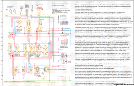
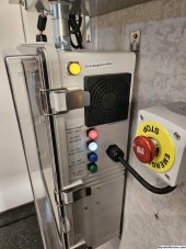
Just to update my last post. I've made some changes on the emergency shutdown controller to make it more reliable and convenient to use. Now I'm able to change the state of each WiFi relay with momentary push buttons also (in case someone else need to manually control the unit without having access to the smart home system). The current states of each WiFi relay are now visible with the integrated LED's in each of the push buttons. Now there are 4 buttons to switch battery relays on/off, AC-in contactors on/off, PVRSS on/off and the 4th button is to activate the emergency shutdown manually.

On top of that, I've installed a self-holding relay (K14) in series to the emergency switches. So, if someone shutting down the system (e.g. with one of the emergency shutdown buttons or smoke detector or remote via WiFi relay), it will not automatically reconnect again if the emergency situation is solved. This is to prevent a high inrush current from the batteries to the inverters by accidentally forgetting to switch all the batteries off before releasing the emergency situation - which may destroy the inverters capacitors! For this reason, a 5th push button is installed with the self-holding relay to manually release the emergency situation. This button should only be pressed if all batteries are (soft) switched off. After the emergency release button is activated, the batteries could be switched on again to let the current limiter do it's job.

I also implemented temperature controlled cooling fans for the 600A battery relays because they will get really hot in this small enclosures...

Here is the final schema of the controller:
controller-schema.png

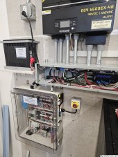
This is how the system looks like so far:
20230929_084351.jpg20230929_084450.jpg
20230929_084503.jpg20230929_084608.jpg
20230929_084624.jpg
 
I harvest the americium buttons from smoke detectors and am always amazed that tou can still get the non-networked units. $3-4 each at HabitatForHumanity stores, flea markets, etc.
@Madco ... What is it that you do with these (radioactive) materials?

I "recycle" everything, so all the electronics boards & such go into a box to later harvest off the semiconductor parts with a heat gun. These go to fill my electronics & semiconductor bins ...

Will have to identify (and watch out for) these americium buttons ...
 
Back
Top