diy solar

diy solar

PV arc fault (AF) and ground fault (GF) detection - DIY someone?

fmeili1

Solar Enthusiast
Joined
Jan 19, 2022
Messages
335
Location
Arizona, Mohave County
I was thinking about whether you could build an AFDD and GFDD detector yourself that is contactless and only operated using a current transformer (this is only about detection, not circuit disconnect after detection, so no AFCI and GFCI devices).

After some research, I found the MNHBB-AFGF sensor from MidNiteSolar which is doing exactly what I want. Unfortunately, it only works with the corresponding MidNiteSolar MPPT chargers. I haven't been able to find a generic AF/GF detector for PV (DC) yet. Here is a picture of this MidNite module.
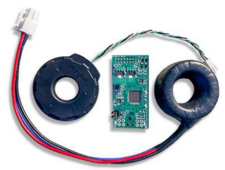
1711155192557.png
After further research, I came across the paper "Arc-Faults Detection in PV Systems by Measuring Pink Noise With Magnetic Sensors". The process doesn't look that complicated and should actually be able to be implemented with an Arduino, for example (FFT and some arithmetic to determine the pink noise). The covered DC voltage and current range from 50V to 300V and 6A to 30A is a perfect fit for typical home PV systems.

The GF detection could be determined relatively easily, as with the MidNite module, using current delta with 2 CTs (one around PV+ and one around PV-). 2 CT's would then be necessary per PV string to cover both AFDD and GFDD. An Arduino could probably control multiple strings (CT's).

Such a device would be very helpful for people like me who own AIO devices that do not have integrated AF and GF detection/disconnects (e.g. EG4-6500EX). If an AF or GF was detected you could use it to disconnect the PV strings with external mechanisms, e.g. either with remotely controlled contactors or with, for example, Tigo TS4-A-2F.

Instead of CTs, possibly a coreless compact and cheap tunnel magnetoresistance (TMR) which are mentioned in the article and are attached to the PV cables on the insulation, could be used. I think the accuracy of the sensor and also the FFT calculation resolution needs not to be very exact and fast to just achieve an ARC detection - but I'm not sure.

In addition to the software challenges (FFT etc.), I see two additional potential problems:
  • With non-isolated inverters (e.g. EG4-6500EX) there is an AC-like ripple signal on the PV lines, which could interfere with the determination of pink noise.
  • The PVRSS system from Tigo uses communication over powerline to control of the remote switches (e.g. TS4-A-2F), which itself is coupled into the PV line using CTs. This signal could overlap with the ARC detection and possibly have a negative impact on the detection.
I have 8 strings and it would be great if I could implement AF and GF detection on the PV side in this simple way (with an Arduino if necessary).

Has anyone ever heard of a project like this?
 
Following
I went looking for stand alone arc fault detectors about a year ago and came up with nothing useful.

There's an obsolete sensor that comes up eBay from time to time, that kit you found, and otherwise you get what's built into an inverter.
 
For someone interested in electronics...

I'm thinking a bit deeper into the idea to DIY a general PV protection circuit which may cover 3 parts in one device:
  • SP: surge protection (like already discussed here)
  • GFD: ground fault detection (and maybe disconnect?)
  • AFD: arc fault detection (and maybe disconnect?)
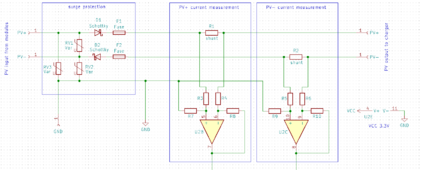
I found that the ESP32-DevKitC microcontroller (about $5) has enough CPU power to do the (complex) arc fault detection calculation, even for more then one PV string. The ground fault detection would be easy because it only needs to compare the PV+ current and the PV- current and if a difference is measured, it's an ground fault. To reduce the number of electronic components, the GF detection could also be done in software.

Here is the rough idea schema:

1711469440375.png
For AFD it would be enough to just measure the current of either PV+ or PV-, but to be able to also implement GFD, both PV+ and PV- needs to be measured independent. Instead of using CT's it's a lot cheaper to just use two shunt resistors (possibly printed on the PCB with about 1 milliOhm). The OPAMP's are required to be able to do a current measurement without (ground) reference.
The output of the OPAMP's could directly be connected to the ESP32 ADC inputs (range 0-3.3V).

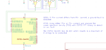
The ESP32 module has 16 ADC so it would be possible to protect/monitor up to 8 individual PV strings by duplicating the above circuit for every PV string.

Example with the possible connection to the ESP32 for just the first string using the two lowest ADC channels 0 and 3 (pin3 and pin4):

1711471339902.png

I think about modularity to develop a separate "probe PCB"'s to handle just one string. A separate "controller PCB" (with the ESP32) would be able to work with up to 8 of the individual string PCB's (I have 8 strings in my installation).

It's just the first rough idea. There are still a ton of questions like:
  • How to generate the 3.3V power supply for the ESP32 and the OPAM's? Is a separate power supply required? Would it be possible to use a buck converter for the wide range of PV voltage (e.g. 10VDC to 500VDC) and feed the circuit just with the PV power. But this would stop the ESP32 working at night (or very bad weather) and the integrated WiFi in the ESP32 would not be accessible without power.
  • Would it be possible to implement a "disconnect" feature also for GF and AF instead of only detecting it (for further processing)? Maybe IGBT's (up to 500VDC) may be used to disconnect the PV. The digital outputs of the ESP32 could be used to control these IGBT's.
  • Because of the different string voltages, the varistors for the SP needs to be selected specifically for each string - no generic solution for each "probe PCB"? Maybe a case could be build where the specific varistors may be clamped from the outside to the circuit to make the "probe PCB generic"?
  • etc.
Any ideas and thoughts about this are more than welcome...

Please let me know if you think this may be the wrong forum for such a project... maybe a Arduino (ESP32) community would be the better place... because it's 100% related to PV, I'm not sure...
 
Also following. Have the Deye/EG4 Solar hybrid mini splits which don't have Arc or Ground fault. Currently (no pun intended!) mitigate this by not having DC wiring on or in house (Edit: I have a Ground mount array), just outside and straight to units.

Refer to

Fonrich and ABB devices seem interesting, not much info on ABB (AC arc fault??) Still some ABB on ebay.

Combined Surge / Arc / Ground fault would be fantastic, but not sure of demand/interest level in the general realm with most devices being UL-1699 going forward??
 
Last edited:
Also following. Have the Deye/EG4 Solar hybrid mini splits which don't have Arc or Ground fault. Currently (no pun intended!) mitigate this by not having DC wiring on or in house (Edit: I have a Ground mount array), just outside and straight to units.

Refer to
I've totally missed this old thread... this forum is (luckily!) so busy with so many search hits, sometimes it's not easy to find matching threads...
Fonrich and ABB devices seem interesting, not much info on ABB (AC arc fault??) Still some ABB on ebay.

Combined Surge / Arc / Ground fault would be fantastic, but not sure of demand/interest level in the general realm with most devices being UL-1699 going forward??
Even if it's not a high demand, I think I'll try it with all three features in one. Maybe it could end up in a separate fun project with the ESP32 sources, the schema and the PCB layout in github or somewhere else (I'm using KiCAD for schema/PCB). JLCPCB may produce the PCB's for around $10 each (I've done this previously with a different circuit, it's super quality and fast service). This may help some of us without integrated SP/AF/GF features. Currently I have some time constraints but I think it may evolve over the next couple of month. Sounds like a possible fun project :cool:

The biggest challenge in my opinion would be the testing phase, specifically to test the reliability of the ARC detection feature...
 
Arc fault is the difficult one, distinguishing low level random noise among higher switching harmonics and RF interference.

I think the (UL?) qualification test involves detecting steel wool burning up in series with the circuit.
 
Arc fault is the difficult one, distinguishing low level random noise among higher switching harmonics and RF interference.
Yes, that's right. But the above mentioned scholar article describes the detection method really nice. I hope it will be possible with a ESP32 and the provided algorithm to detect AF in a reliable way because the higher harmonics are not used to analyze the AF. It looks like the interesting frequencies are below 1kHz in the power spectrum density chart to detect an DC arc. Hopefully the switching harmonics and RF interference which you've mentioned will not disturb too much the detection method...
I think the (UL?) qualification test involves detecting steel wool burning up in series with the circuit.
wow... testing would be the crazy part... luckily UL certification is not a goal of this DIY project - so I think we can skip the steel wool burning part ;)

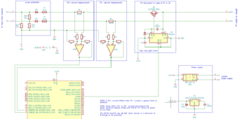
In the meantime I've extended the circuit and added a disconnect IGBT in case a AF or GF will be detected. It makes a lot more sense to not only detect a fault (and process it somewhere else externally) but also disconnect the PV in such a case. Because the IGBT is used at the high side, a gate driver with a boost capacitor is required to lift the voltage about 10-20V over the PV+ voltage to be able to switch the IGBT. I'ts no problem to find an IGBT with 600V max. voltage and 20A max. current.

Two LED connected on two GPIO ports will light up in case of an AF or GF to signal the fault (beside transmitting this info via WiFi/MQTT to somewhere else - in my case my smart home system).

I've also added (just as a draft) a power supply to create the +3.3V and +12V for the ESP32, OPAMP's and gate driver. Maybe I'll find a gate driver which runs with 3.3V to get rid of the additional 12V requirement. For now I've added a 120VAC to 12VDC converter, so the circuit needs a 120VAC power supply - maybe this is not ideal for this application and a different type of DC power source should be used...

1711508015983.png
1711508078483.png
 
Update:
The possible design made some steps forward and I would like to share the current status and ideas.
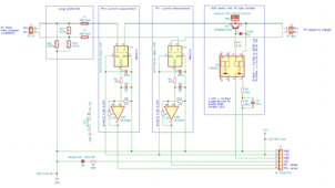
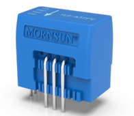
The "probe" circuit now using hall current sensors which is simpler compared to floating shunt measurement and also it's isolated. The IGBT is driven by a photovoltaic optical gate driver. In case an GF and AF will happen, a LED will signal it and the IGBT will stay turned off until the fault is cleared (manually by the controller).
1712237959268.png

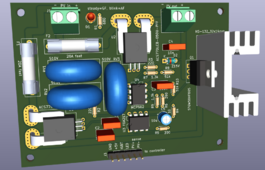
The "probe" PCB for each PV string could look like this - just a first test to get an idea...


1712238091789.png


In my situation I need 8 of these PCB's to protect all strings. Each "probe" PCB will be connected to a central "controller" PCB with 6-wire cable. The controller is able to control between 1-8 "probe" PCB's.

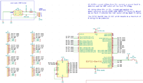
The controller schematic current status:

1712238527154.png

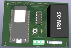
A possible controller PCB might look like this:

1712239106526.png

On the upper side are the 6-pin connectors which will be connected to the "probe" PCB's. A "fault reset" button can clear a detected fault condition (or with software remote via WiFi).

Any feedback is more than welcome!

Next, I will order some components to do a first breadboard test for just one string to find out if the concept in general is working and if it's worth to continue the project.
 
Last edited:
I am concerned that having 2 separate current sensors would cause nuisance trips due to drift between them. Why not just put both positive and negative PV wires through one Lem hall sensor just like it's done with AC GFCI devices?
 
I am concerned that having 2 separate current sensors would cause nuisance trips due to drift between them. Why not just put both positive and negative PV wires through one Lem hall sensor just like it's done with AC GFCI devices?
This is good idea! The main reason, why I've chosen the PCB mounted hall sensors is because it reduces the additional components which have to be mounted off the PCB and DC CT's are more expensive compared to these PCB mounted hall sensors. For the AF detection I need a current measure either from PV+ or PV- anyway, so one PCB hall current sensor is still required (or a 2nd external CT).
But anyway, you're right it would reduce the possible drift for GF detection. Maybe I will be able to find a PCB mounted DC CT where I may route both PV+ and PV- tracks through a single component (I'm not sure if something exists). If not I need to add a connector for a traditional external DC CT.
 
I am concerned that having 2 separate current sensors would cause nuisance trips due to drift between them. Why not just put both positive and negative PV wires through one Lem hall sensor just like it's done with AC GFCI devices?

Yes, would expect allowed leakage current to be a percentage of total current, due to gain error between sensors.
Could calibrate, but would drift as you say. In fact, I find hall effect drifts badly, gets an offset after single use for scope probes.

With a light bulb as load, you only get 1 mA shock before it trips, but 2 HP motor and you get 30 mA shock.

Both wires through single sensor should cancel magnetic fields.

Hall effect? Are you designing DC GFCI? (Yes, it's for PV, dummy!)

OK, two wires for one sensor. I have a concern that just wire near hall effect would not balance interaction. Does it work to wrap both wires around a core, producing a magnetic field in a gap (but no induction of current because not AC), then single hall effect device in gap?

The cancelled fields may also reduce issue of hall effect drift. But when subjected to high current from a hard fault, that might cause drift.

Is hall effect used in any commercial DC GFCI devices? Is drift not an issue at the 1A scale, only at the mA scale I see for probes?

There are other magnetic sensing devices. I'm seeing Flux Gate for sensors at work. A 15 kHz excitation field is applied to two rod shaped non-linear cores. Magnetization due to offset by externally applied field means one phase goes more into saturation than the other, and a second winding around both cores (wound opposite on one) gets induced signal from carrier.
 
There are other magnetic sensing devices. I'm seeing Flux Gate for sensors at work. A 15 kHz excitation field is applied to two rod shaped non-linear cores. Magnetization due to offset by externally applied field means one phase goes more into saturation than the other, and a second winding around both cores (wound opposite on one) gets induced signal from carrier.
Interesting. Will have to look into those.
 
They are used in the Magnetic Field Cancellation systems we have around SEM.
Needs suitable filter to block carrier so it isn't driven into compensation coils.
But too low an LPF corner, and phase shift makes compensation ineffective.
So with a sensor that had 5 kHz not 1 kHz bandwidth, I added a second-order 5kHz filter and that helped.
 
I am commenting here mainly to follow where this goes. I would like to add Arc Fault to my DC array at some point. It is not technically over a living space and it has all the other protections.

I am surprised that no company has produced a reasonable stand alone arc fault protection box for DC PV. All the ones I have found are very expensive combiner boxes for large arrays.

This could be made into a good product, but then UL testing and liability become big issues.

For lower voltage arrays, under 150 volts, I would think a MOSFET would be a better switch than an IGBT. IGBT's sill have the 0.5 volt drop where a MOSFET switch is just a very small resistance.

Another thought I had, make this protection detector send out the Sun Spec signal for RSD devices. If it detects any fault (Arc, GF, RSD command) then stop sending the signal and the RSD devices at each panel just disconnects. That is even greater safety as it could also stop an arc to ground or between conductors that opening the line to the charge controller can't stop. Then just use something like a Tigo RSD box at each panel and those are already tested and approved devices. You just need to interrupt the signal from the "keep alive" transmitter when a fault is detected.
 
I am commenting here mainly to follow where this goes. I would like to add Arc Fault to my DC array at some point. It is not technically over a living space and it has all the other protections.

I am surprised that no company has produced a reasonable stand alone arc fault protection box for DC PV. All the ones I have found are very expensive combiner boxes for large arrays.
I'm also surprised and that's the main reason for this project.
This could be made into a good product, but then UL testing and liability become big issues.
The goal is to try to make a standalone AF, GF, SP device for hobby usage (so far, I don't care about UL testing, etc.). It should be modular to be easily being modified for specific needs (max. Voc, max. PV current, 1 to 8 strings, with or without existing PVRSS).
For lower voltage arrays, under 150 volts, I would think a MOSFET would be a better switch than an IGBT. IGBT's sill have the 0.5 volt drop where a MOSFET switch is just a very small resistance.
The optical gate driver is also able to drive a MOSFET. So maybe it could be done as an option to use an IGBT (for high PV string voltage) or a MOSFET for <150V strings.
Another thought I had, make this protection detector send out the Sun Spec signal for RSD devices. If it detects any fault (Arc, GF, RSD command) then stop sending the signal and the RSD devices at each panel just disconnects. That is even greater safety as it could also stop an arc to ground or between conductors that opening the line to the charge controller can't stop. Then just use something like a Tigo RSD box at each panel and those are already tested and approved devices. You just need to interrupt the signal from the "keep alive" transmitter when a fault is detected.
In my case, I already have a Tigo PVRSS with TS4-A-2F, so I don't need the IGBT/MOSFET switch at all. I'm planning to implement a dry contact relay also to just switch off the power of the Tigo transmitter in case of an fault detection - maybe selectable via a jumper which option should be used. But for someone who does not have a module level PVRSS, the electronic switch would be a nice option.

I'm still thinking if it's possible to also integrate the surge protection in a more consistent way. If a surge event happens and the varistor(s) are short they may be just destroyed (in case of a huge sure), or they may be setting back to normal if the surge is over. Maybe the fuses will also trip (depending of the charge controller circuit when one of the entries will be connected to ground via a varistor). I don't see a reliable way to detect if such an event happened and if the varistors are still ok and what's the current situation. This is different compared to the AF and GF which is processed by the ESP32.
 
Interesting. Will have to look into those.

"Flux Gate" is for ambient magnetic fields. Seems to work on same principle as "Magnetic Amplifier" except that uses magnetic field from a coil of wire. In either case, DC or slow moving field modulates an AC current.

I think Magnetic Amplifier might work as your GFCI detector. Two coils for PV+/PV- cancel each other. Unlike AC GFCI, they don't have an AC component to induce current in a secondary. Instead, they gate an AC excitation signal allowing more of the positive pulse than the negative (or vice versa) by shifting where on the BH curve it operates.

 
The "probe" PCB for each PV string could look like this - just a first test to get an idea...
Noticed the PCB is missing beefy ground connection for MOV surge current to go to ground. I would upsize input terminal block and pcb tracks around MOVs. We're talking 10kA surge currents there.
 
Back
Top