You are using an out of date browser. It may not display this or other websites correctly.
You should upgrade or use an alternative browser.
You should upgrade or use an alternative browser.
PV arc fault (AF) and ground fault (GF) detection - DIY someone?
- Thread starter fmeili1
- Start date
I would place MOVs on separate PCB by themselves. They are most likely ones to catch fire so it would prevent destroying remainder of your board. Make a separate "come together" SPD box to where all in/out lines terminate to a common ground block. Then fan out all the lines to your solar equipment after it. Make it a single point ground. For total protection all your power, data and contact closure lines need to pass through that common point. Including USB / Ethernet. Place ferrite rings right before inverter terminals to reduce common mode surges from EM pulses.
fmeili1
Solar Enthusiast
I've put filled copper zones on both sides of the PCB which are connected to GND (DC GND is connected to PE). These zones fill the complete free surface of each PCB side and all GND connected components are connected to these zones to make a bigger cross-section and it also shields a bit.
To make the cross-section bigger for the high current tracks, I've removed them from the silkscreen to be able to put solder to these tracks later (fuses, PV connectors, varistors, IGBT, current sensors). Typical PCB copper has only 1 or 2 oz/sqft (34 or 69µm) which would be too less anyway. I'm using JLCPCB manufacturer where I can choose between these two sizes.
The idea to put just the MOV's (maybe together with the fuses) to a separate PCB would give some pros. But it would be an additional required PCB... need to think about it... to make it a good and safe solution, it may be the best to do...
As you've mentioned, in the meantime I've changed the "probe PCB" and put a hall CT coil to measure the GF situation. I found only a coil with 3 through wires (two would have been enough) so I can only use 2/3 of the rated amps of the coil which results in 16.6A max. PV current - which should be enough for most cases (my strings have 10A max.).
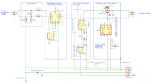
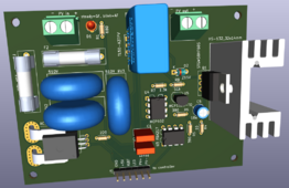
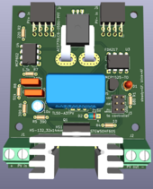
On the controller I've added a DPDT relay to be able to drive an external PVRSS (like Tigo). In case of using an external PVRSS, a bridge between Drain/Source or Collector/Emitter can be soldered instead of the IGBT or MOSFET. This is the current "controller PCB":
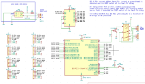
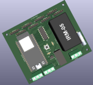
To make the cross-section bigger for the high current tracks, I've removed them from the silkscreen to be able to put solder to these tracks later (fuses, PV connectors, varistors, IGBT, current sensors). Typical PCB copper has only 1 or 2 oz/sqft (34 or 69µm) which would be too less anyway. I'm using JLCPCB manufacturer where I can choose between these two sizes.
The idea to put just the MOV's (maybe together with the fuses) to a separate PCB would give some pros. But it would be an additional required PCB... need to think about it... to make it a good and safe solution, it may be the best to do...
As you've mentioned, in the meantime I've changed the "probe PCB" and put a hall CT coil to measure the GF situation. I found only a coil with 3 through wires (two would have been enough) so I can only use 2/3 of the rated amps of the coil which results in 16.6A max. PV current - which should be enough for most cases (my strings have 10A max.).


On the controller I've added a DPDT relay to be able to drive an external PVRSS (like Tigo). In case of using an external PVRSS, a bridge between Drain/Source or Collector/Emitter can be soldered instead of the IGBT or MOSFET. This is the current "controller PCB":


fmeili1
Solar Enthusiast
I followed @AntronX 's advice and build a separate "SP PCB" just for the SP. I've made this design modular to save space and by connecting 1-8 units side by side with pin header connectors to run the PE/earth like a bus through all of the units. This will make wiring easier and PE only needs to be connected to just one of the units. On the other units, the PE/earth screw connector terminal does not need to be mounted.
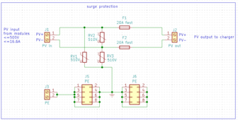
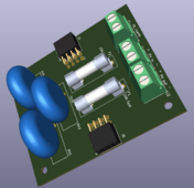
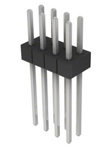
The PE bus connection is done by 8 pin header connector sockets (2x4) which are good for 24 amps. They could be connected in series, placed side by side, with a through hole connector header like this:
Both sides of the PCB using copper zones for PE/earth to be able to withhold the amps.
I think about 3D print a snap in case for the units. I suspect that in the event that the MOV explodes and hot parts fly around, a plastic housing would still provide enough protection because the MOV would then probably no longer produce heat after the initial shock because it would then be defective... but I'm not sure.
Now I need to redesign the "probe PCB" and find an idea how to modularize it also (stackable?) in a way to be able to easy integrate the SP units to the GF/AF and how to attache them to the "controller PCB". I don't want to make a design with too many required external cable connections and I want to be able to integrate it easy in an outer case...


The PE bus connection is done by 8 pin header connector sockets (2x4) which are good for 24 amps. They could be connected in series, placed side by side, with a through hole connector header like this:

Both sides of the PCB using copper zones for PE/earth to be able to withhold the amps.
I think about 3D print a snap in case for the units. I suspect that in the event that the MOV explodes and hot parts fly around, a plastic housing would still provide enough protection because the MOV would then probably no longer produce heat after the initial shock because it would then be defective... but I'm not sure.
Now I need to redesign the "probe PCB" and find an idea how to modularize it also (stackable?) in a way to be able to easy integrate the SP units to the GF/AF and how to attache them to the "controller PCB". I don't want to make a design with too many required external cable connections and I want to be able to integrate it easy in an outer case...
There have been house fires caused by overheated MOVs inside plastic power strips.plastic housing
fmeili1
Solar Enthusiast
ok... bad idea...There have been house fires caused by overheated MOVs inside plastic power strips.
Hedges
I See Electromagnetic Fields!
- Joined
- Mar 28, 2020
- Messages
- 20,690
MOV fail short. Easy fix is buy MOV with thermal protection in series.
Those are available 2 lead, or 3 lead so status available to monitor or light an indicator.
I suppose a proper fuse in series would be good, since electronic gizmos can't be relied on if SHTF.
Those are available 2 lead, or 3 lead so status available to monitor or light an indicator.
I suppose a proper fuse in series would be good, since electronic gizmos can't be relied on if SHTF.
fmeili1
Solar Enthusiast
Ok, after watching this video, I've will follow your advice and changed the MOV's into TMOV's (but without indicator, because the "SP PCB" does not have an additional power source). Now I will again consider just a 3D plastic cover over the "SP PCB" which may now be enough... a rest of a risk will remain... I have not added additional fuses in series to each TMOV because the max. PV current is 10A and in case of a huge surge (lightning near by?), the fuse would anyway be too slow - I guess.
I've changed the PCB's to be more modular. The "SP PCB" could be used stand alone (without the "probe PBC" for GF/AF) and optionally cascaded side by side for 1-n strings. In stand alone usage, the back pin sockets which optionally connects to the "probe PCB" (GF/AF) are not required to mount in this case. The screw terminals will be used for PV in and PV out.
The side pin sockets are only required to mount if more than one "SP PCB" (more strings) will be used (chaining). If chained, only one module's PE screw terminal needs to be connected to PE and the other will get their PE via the pin sockets.
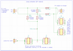
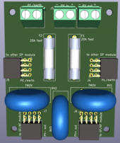
In case the addition (optional) GF/AF will be used, the "probe PCB" will be connected "under" (behind) the "SP PCB". In this case, the PV input will be used from the "SP PCB" screw terminal and the PV output from the "probe PCB", the not used screw terminal don't need to be mounted in this case.
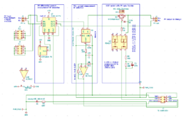
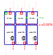
A setup for 3 strings with just the SP module may have the following layout. In this case the wiring for PV in and PV out will be done from one side:
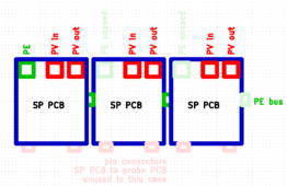
A setup for 3 strings with all modules (beside the "controller PCB") may have the following layout. No additional wires are required which makes the installation easy and everything could be placed in one case (where each SP PCB has it's own cover over the TMOV's). In this case the wiring for PV in and PV out will be done from opposite sides:
I still need to find a good way to mount and connect the central "controller PCB" to all the "probe PCB's".
I've changed the PCB's to be more modular. The "SP PCB" could be used stand alone (without the "probe PBC" for GF/AF) and optionally cascaded side by side for 1-n strings. In stand alone usage, the back pin sockets which optionally connects to the "probe PCB" (GF/AF) are not required to mount in this case. The screw terminals will be used for PV in and PV out.
The side pin sockets are only required to mount if more than one "SP PCB" (more strings) will be used (chaining). If chained, only one module's PE screw terminal needs to be connected to PE and the other will get their PE via the pin sockets.


In case the addition (optional) GF/AF will be used, the "probe PCB" will be connected "under" (behind) the "SP PCB". In this case, the PV input will be used from the "SP PCB" screw terminal and the PV output from the "probe PCB", the not used screw terminal don't need to be mounted in this case.


A setup for 3 strings with just the SP module may have the following layout. In this case the wiring for PV in and PV out will be done from one side:

A setup for 3 strings with all modules (beside the "controller PCB") may have the following layout. No additional wires are required which makes the installation easy and everything could be placed in one case (where each SP PCB has it's own cover over the TMOV's). In this case the wiring for PV in and PV out will be done from opposite sides:

I still need to find a good way to mount and connect the central "controller PCB" to all the "probe PCB's".
fmeili1
Solar Enthusiast
I think I found a working modular setup for the whole device.
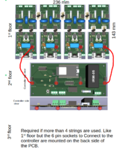
The first 4 strings will fill the bottom of a case. The "controller PCB" will go to the 2nd floor and connect with long pin headers to the "probe PCB's". In case more than 4 strings will be used, the 3rd floor could hold the same PCB layout like the first floor. In this case the pin headers of the 3rd floor have to be soldered to the back side of the upper PCB's.
The whole device for 8 strings for SP, GF, AF would fit in a case of the size 250mm x 150mm and 80mm height. A device for 4 strings would have a height of 40mm (the size would be enough to install a small cooling fan for the MOSFET's - after the hint from @GXMnow I've replaced the IGBT with MOSFET because they produce half of the loss at <20 AMPS). The PE side pin headers from the 1st floor have to be connected with a 6 pin cable to the 3rd floor PE side connector in case if using more than 4 strings.
If someone would use an external PVRSS instead of the MOSFET to disconnect the PV side, the MOSFET and the heatsink are not required on the "probe PCB" and the case could be even smaller.
The case may be 3D printed with horizontal slide mounts to be able to slide in the PCB's for the 3rd layer.... I have to think about it a bit more...
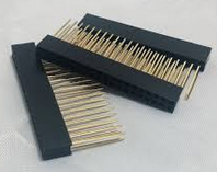
The connection between the floors should be done with long pin header space (stacking) connectors like these:
The design may have potential and may work - still not sure. Depending on my spare time I will try to dig deeper into it and I'm always happy about your feedback!
The first 4 strings will fill the bottom of a case. The "controller PCB" will go to the 2nd floor and connect with long pin headers to the "probe PCB's". In case more than 4 strings will be used, the 3rd floor could hold the same PCB layout like the first floor. In this case the pin headers of the 3rd floor have to be soldered to the back side of the upper PCB's.
The whole device for 8 strings for SP, GF, AF would fit in a case of the size 250mm x 150mm and 80mm height. A device for 4 strings would have a height of 40mm (the size would be enough to install a small cooling fan for the MOSFET's - after the hint from @GXMnow I've replaced the IGBT with MOSFET because they produce half of the loss at <20 AMPS). The PE side pin headers from the 1st floor have to be connected with a 6 pin cable to the 3rd floor PE side connector in case if using more than 4 strings.
If someone would use an external PVRSS instead of the MOSFET to disconnect the PV side, the MOSFET and the heatsink are not required on the "probe PCB" and the case could be even smaller.
The case may be 3D printed with horizontal slide mounts to be able to slide in the PCB's for the 3rd layer.... I have to think about it a bit more...

The connection between the floors should be done with long pin header space (stacking) connectors like these:

The design may have potential and may work - still not sure. Depending on my spare time I will try to dig deeper into it and I'm always happy about your feedback!
Last edited:
Quattrohead
Solar Wizard
Look up FR-DCMG-AS4A DC Arc-Fault Detector
It is the device used in the EG4 18kpv inverter.
It is the device used in the EG4 18kpv inverter.
fmeili1
Solar Enthusiast
Thanks for the hint, that's interesting. When I was searching for a stand alone AF detector, I was not able to find this one. Looks very promising and modular. Could not find any price information. I've done an inquiry to the manufacturer about 1-2 units for private / hobby / DIY usage and will see if/how they will answer.Look up FR-DCMG-AS4A DC Arc-Fault Detector
It is the device used in the EG4 18kpv inverter.
ksmithaz1
Solar / EV Junkie
Out of curiosity, how do you plan on testing this once/if you build it? Also, do you 'tune' it in any way or does the ESP32 just do it's thing? I guess if it was easy, they'd be stamping them out in China by now.
fmeili1
Solar Enthusiast
In case this project idea would really come true, testing will be the challenge. Testing the GF (Ground Fault) would be the only easy part by just using a resistor on the PV line and connect either PV+ or PV- via the resistor to the ground to simulate this fault type.Out of curiosity, how do you plan on testing this once/if you build it? Also, do you 'tune' it in any way or does the ESP32 just do it's thing? I guess if it was easy, they'd be stamping them out in China by now.
But I'm not sure if I will be able or willing to test the SP (Surge Protection) and the AF (Arc Fault) detection in real situations. The AF detection may be tested with simulated data by using a given test power spectrum of an DC PV Arc and check if the algorithm running on the ESP32 would detect it. Doing a SP test would require crazy test equipment... I think I can't do this... mhh, maybe possible with a Tesla coil... I think not in this life...
fmeili1
Solar Enthusiast
Yeah, I'm also not crazy about the pin headers. I think it will work with enough pins in parallel and protecting the PCB's against moving - but it's still not designed for such a use case. Maybe I can find a better but equally simple way with a different type of connector...I just don't like those pin headers used for ground interconnect. But your method will probably work.
ksmithaz1
Solar / EV Junkie
But I'm not sure if I will be able or willing to test the SP (Surge Protection) and the AF (Arc Fault) detection in real situations. The AF detection may be tested with simulated data by using a given test power spectrum of an DC PV Arc and check if the algorithm running on the ESP32 would detect it. Doing a SP test would require crazy test equipment... I think I can't do this... mhh, maybe possible with a Tesla coil... I think not in this life...
I was thinking you could build a simple apparatus with a fine gear that gradually opened a small gap between two conductors to create an arc. I guess since the devices seem to be hard to find, a tester for them would be even harder. One would assume once the current starts arcing across the gap, the detector should shut things down in fairly short order. I poked around only a littile; I didn't see a standard testing based on having an actual arc, Xmm arc at Xv Xa or some such. Great project.
fmeili1
Solar Enthusiast
There are many scholarly articles out there which discussing and testing different arc detection mechanisms for PV (I'm not an expert in this area). For testing, they all build such a spark gap device. But I think with my limited hobby equipment and time (and I don't want to ruin my productive MPPT charger with arc testing) I don't see a realistic chance to really test this in depth. Because of these testing challenges, I'm still not sure if this project idea will ever come true - it's still in the "does it make sense - is it possible and realistic" phase. I ask myself how much value may such a device have if I never had a chance to test it in real conditions?! Still need to do some more research before really buying parts and producing PCB's...I was thinking you could build a simple apparatus with a fine gear that gradually opened a small gap between two conductors to create an arc. I guess since the devices seem to be hard to find, a tester for them would be even harder. One would assume once the current starts arcing across the gap, the detector should shut things down in fairly short order. I poked around only a littile; I didn't see a standard testing based on having an actual arc, Xmm arc at Xv Xa or some such. Great project.
fmeili1
Solar Enthusiast
I've got feedback from the manufacturer (Fonrich Ltd, Shanghai). They are willing to send units (even just one) for private use to the US. The system is modular. Here is an example picture of a setup with two 4 string hall sensors in series. Up to 6 of these sensors (24 strings) could be connected to one controller.Look up FR-DCMG-AS4A DC Arc-Fault Detector
It is the device used in the EG4 18kpv inverter.
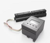
The controller is available with different models. Only three of the controllers are able to use the hall sensor (I don't know what are the others for - maybe just for monitoring which I don't care because I monitor already with SA).

Because I already have an external Tigo PVRSS system, I would choose the model with the Relay/Contactor which will be activated in case of an arc fault detection. Unfortunately, this model is the only one which requires an external 24VDC power source - but this does not really hurt.
All controller models are able to communicate via RS485 protocol. The company sent me the technical documentation where even the protocol is described in detail.
Very interesting is the price:
FR-DCMG-AS4A Hall Sensor: $28.50
FR-DCMG-MMPS Main Controller: $58.00
Express Shipping Cost & Bank wire charge: $98.00
Maybe they offer cheaper shipping (they don't have an US distributor) - but I'll have to find out.
I think, because of this price it makes no sense to continue pursuing the DIY project idea (at least the AF part). It will not be possible to build it for this price and these units are already tested and certified and are actively used in the EG4 18kpv as you've mentioned.
I think I will reduce the project to just do the SP - maybe the GFD part would also make sense but still not sure about it. The GFD part could be done without ESP32 and software by just using an OpAmp to detect a difference between PV+ and PV- current, which would make the GFD circuit easier and cheaper.
Similar threads
- Replies
- 2
- Views
- 299
- Replies
- 5
- Views
- 340
- Replies
- 52
- Views
- 3K


