diy solar

diy solar

Solar Assistant power backfeed from EG4

dmkjr

Solar Enthusiast
Joined
Mar 19, 2023
Messages
205
Location
South Carolina
Just wanted to share I found a cheap product to help with those that are getting power back from the micro-usb to the Solar Assistant. While it hasn't damaged the unit through the USB port it prohibits the unit from rebooting should it lose power for any reason. It's plugged into a circuit that is controlled by the inverter so when the unit switches modes from SBU (Solar/Battery/Utility) to SUB (Solar/Utility/Battery) -- no matter how quick the transition is -- the solar assistant PI4 will reboot. This piece of equipment has stopped the power feeding back, which allows the unit to reboot without issue.


Blocks power through the USB pins but allows data still. Reverse from the cables that are abundantly available that stops communications but allows power.
 
You would think this is a wide spread issue, I think mine is doing this as well. If I shut down both inverters the screens stay lit up with an error until I disconnect the Pi.
 
Last edited:
Just wanted to share I found a cheap product to help with those that are getting power back from the micro-usb to the Solar Assistant. While it hasn't damaged the unit through the USB port it prohibits the unit from rebooting should it lose power for any reason. It's plugged into a circuit that is controlled by the inverter so when the unit switches modes from SBU (Solar/Battery/Utility) to SUB (Solar/Utility/Battery) -- no matter how quick the transition is -- the solar assistant PI4 will reboot. This piece of equipment has stopped the power feeding back, which allows the unit to reboot without issue.


Blocks power through the USB pins but allows data still. Reverse from the cables that are abundantly available that stops communications but allows power.
What I did after I had a Pi4 memory fried was using 2 of these RS232 isolators and a small UPS. For the batteries to USB I had an RS485 isolator. That monitoring setup worked flawlessly whenever I switched from grid to inverter power and vice versa without frying any device or losing power.

Now I've switched to using small Atom lite ESP32s running a TCP to serial bridge (Tasmota made that easy) with the same isolators but less "power hungry" and a much smaller USB UPS that powers them via an USB hub.
 
You would think this is a wide spread issue, I think mine is doing this as well. If I shut down both inverters the screens stay lit up with an error until I disconnect the Pi.
You are using the OTG port. The USB port from the Pi provides enough power to keep the screen on and is NOT isolated. I would use the RS232, an RS232 isolator and the RS232 to USB-A adapter instead.
 
What I did after I had a Pi4 memory fried was using 2 of these RS232 isolators and a small UPS. For the batteries to USB I had an RS485 isolator. That monitoring setup worked flawlessly whenever I switched from grid to inverter power and vice versa without frying any device or losing power.

Now I've switched to using small Atom lite ESP32s running a TCP to serial bridge (Tasmota made that easy) with the same isolators but less "power hungry" and a much smaller USB UPS that powers them via an USB hub.
Why did you use 2 RS232 isolators and not one, unless your connecting to multiple inverters? I'm trying to get mine setup right for the 6500ex. I was going to use a usb to rs232, a rs232 isolator you linked to, then rs232 to rj45 to the rs232 port on the inverter, as well as an ac power supply to help further isolate things.

Just going off what others who know much more about this than I do, this might be the right setup to avoid damaging the comm port on the 6500ex as mentioned by ss and eg4 in another thread, even SA said the 6500ex has a cheap ch340 chip.
 
Why did you use 2 RS232 isolators and not one, unless your connecting to multiple inverters? I'm trying to get mine setup right for the 6500ex. I was going to use a usb to rs232, a rs232 isolator you linked to, then rs232 to rj45 to the rs232 port on the inverter, as well as an ac power supply to help further isolate things.
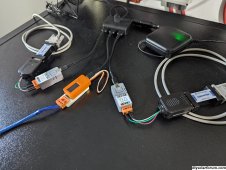
Yeah, one per inverter. This is how it looks now:
1000010287.jpg

The grey things are m5stack Atom lite with the RS232 base. Each of these connects to an isolator which connects to an inverter. The orange thing is an M5Stick connected to a RS485 isolator that connects to a bus where the battery comms wires join together. The small black box with a green light is the 2000mAh UPS linked before.
 
Yeah, one per inverter. This is how it looks now:
View attachment 180254

The grey things are m5stack Atom lite with the RS232 base. Each of these connects to an isolator which connects to an inverter. The orange thing is an M5Stick connected to a RS485 isolator that connects to a bus where the battery comms wires join together. The small black box with a green light is the 2000mAh UPS linked before.
Why do connect to both inverters? I thought all the data comes from one, unless you are not split phase.
 
You get far more data from the second and subsequent inverters by direct connecting them instead of using the parallel data, apparently that is rather limited.
 
I send 4 queries to each inverter: Q1, QPIRI, QPGS1 or QPGS2, and QPIGS. Most of the data is the same, but some differences:

-Q1: has temperatures info, fan speed, fan locked status, and the GPIO13 status. Each inverter has different values for this query.
-QPIGS has the AC output voltage for each. They vary slightly, but when something using a lot of power on one leg is turned on...
-QPIRI only differs in the battery type (EG4 vs USE) and the output mode (2P1, 2P2), so I could just query one inverter for it.
-QPGS1/QPGS2 are consistently the same. I could just send them to one inverter also.

Oh, and almost forgot that there's also the sending commands that change state, not just query data. Many take an inverter number as parameter, others don't. For instance, POPxx (change output source priority, i.e., USB, SBU, SUB, where xx is the mode) can be sent to one of them and, if accepted, the other one will pick up the setting too. Others like PDx (turn off the display, the x is just an x), have to be sent to each individual inverter.
 
Last edited:
I send 4 queries to each inverter: Q1, QPIRI, QPGS1 or QPGS2, and QPIGS. Most of the data is the same, but some differences:

-Q1: has temperatures info, fan speed, fan locked status, and the GPIO13 status. Each inverter has different values for this query.
-QPIGS has the AC output voltage for each. They vary slightly, but when something using a lot of power on one leg is turned on...
-QPIRI only differs in the battery type (EG4 vs USE) and the output mode (2P1, 2P2), so I could just query one inverter for it.
-QPGS1/QPGS2 are consistently the same. I could just send them to one inverter also.

Oh, and almost forgot that there's also the sending commands that change state, not just query data. Many take an inverter number as parameter, others don't. For instance, POPxx (change output source priority, i.e., USB, SBU, SUB, where xx is the mode) can be sent to one of them and, if accepted, the other one will pick up the setting too. Others like PDx (turn off the display, the x is just an x), have to be sent to each individual inverter.
You do all this through Solar Assistant? If so, I need to dive more heavily into that program...sounds like there is some custom script command running, very cool.

Also, are you running 6500ex's or another inverter? Thanks for answering my questions.

EDIT: Studying your picture again are you even running a Pi and SA? Or are you running these queries through the Atom's from somewhere else via tcp? I'm intrigued.

EDIT #2: Studying your first post, so you have like an arduino setup with io to the atoms...now I'm super intrigued.
All this went past me, on first read, my focus was on figuring out power supply/data cable isolation and which data cable to use.
 
Last edited:
You do all this through Solar Assistant? If so, I need to dive more heavily into that program...sounds like there is some custom script command running, very cool.

Also, are you running 6500ex's or another inverter? Thanks for answering my questions.

EDIT: Studying your picture again are you even running a Pi and SA? Or are you running these queries through the Atom's from somewhere else via tcp? I'm intrigued.

EDIT #2: Studying your first post, so you have like an arduino setup with io to the atoms...now I'm super intrigued.
All this went past me, on first read, my focus was on figuring out power supply/data cable isolation and which data cable to use.

I'm using something I wrote -> https://github.com/gonzalop/wombatt. I run the monitor-inverters and monitor-batteries commands, that connect to the TCP addresses and ports served by the 2 Atoms connected to the RS232 in the EG4 6500 inverters and the M5Stick connected to the batteries RS485. The software publishes the info from the queries to MQTT, which feeds Home assistant. The template for the dashboard I use is in the GitHub repo too.

The three gadgets run Tasmota. The atoms use the TCP to RS232 bridge and the M5Stick uses the TCP to modbus bridge.
That's super cool. I saw the cell output on your github page. To my understanding, which is limited at the moment, is where SA lacks on its own thus the need for BMS tools which is inconvenient, or your method which is convenient. I'm going to try an set this up for fun and better monitoring, and just to see if I can do it. Thanks for your help. I'll try not to inundate you with questions (which I still have many) unless absolutely necessary.
 
Yeah, one per inverter. This is how it looks now:
View attachment 180254

The grey things are m5stack Atom lite with the RS232 base. Each of these connects to an isolator which connects to an inverter. The orange thing is an M5Stick connected to a RS485 isolator that connects to a bus where the battery comms wires join together. The small black box with a green light is the 2000mAh UPS linked before.
So the RS485 isolator plugs into the end daisy chained batt (I assume LifePower4's/LL's as mentioned on your github page) in the server rack, via the two wires...correct?
 
So the RS485 isolator plugs into the end daisy chained batt (I assume LifePower4's/LL's as mentioned on your github page) in the server rack, via the two wires...correct?
From each battery RS485 I get 2 wires, all of them are connected using wagos, and from the wagos 2 wires come out which connect to the RS485 isolator. I use 1 ethernet cable for 4 batteries (see https://diysolarforum.com/threads/r...2-pieces-of-ethernet-cable-and-2-wagos.66939/), then one more piece for 1 battery. Currently I'm not monitoring battery #1 (master).
 
From each battery RS485 I get 2 wires, all of them are connected using wagos, and from the wagos 2 wires come out which connect to the RS485 isolator. I use 1 ethernet cable for 4 batteries (see https://diysolarforum.com/threads/r...2-pieces-of-ethernet-cable-and-2-wagos.66939/), then one more piece for 1 battery. Currently I'm not monitoring battery #1 (master).
I'm getting wombatt setup and was wondering if you use the "supervisor" service shown in the youtube video, or another way to poll the data.
EDIT: Oh, nevermind, I think I can handle the poll times via yaml or something in HA...still figuring it out. Thanks.
 
Last edited:
I'm getting wombatt setup and was wondering if you use the "supervisor" service shown in the youtube video, or another way to poll the data.
EDIT: Oh, nevermind, I think I can handle the poll times via yaml or something in HA...still figuring it out. Thanks.
I ran 2 instances of wombatt in a terminal (tmux), one for inverters one for the batteries.
 
I run the monitor-inverters and monitor-batteries commands, that connect to the TCP addresses and ports served by the 2 Atoms...
This is where I am stuck. I can't run /dev/ttyS0 I don't think because they are not physically attached (if I have that right). What do you put in place of /dev/ttyS0 for <device>:
<monitors> ... <device>,<command1[:command2:command3...]>[,<mqtt_prefix>].
E.g. /dev/ttyS0,QPIRI:QPGS1,eg4_1
 
This is where I am stuck. I can't run /dev/ttyS0 I don't think because they are not physically attached (if I have that right). What do you put in place of /dev/ttyS0 for <device>:
<monitors> ... <device>,<command1[:command2:command3...]>[,<mqtt_prefix>].
E.g. /dev/ttyS0,QPIRI:QPGS1,eg4_1
You mean when using TCP? In that case you need to poll the TCP to serial bridge port on the device connected to the inverter(s):

Code:
wombatt monitor-inverters --mqtt-broker tcp://mqtt:1883 --mqtt-user <youruserhere> --mqtt-password <yourpasswordhere> tasmota-inverter1:8232,Q1:QPIRI:QPGS2:QPIGS,eg4_1 tasmota-inverter2:8232,Q1:QPIRI:QPGS1:QPIGS,eg4_2 -T tcp
where tasmota-inverter1 and tasmota-inverter2 are the names I assigned to the devices connected to the inverters. You can use an IP address instead.
 
Back
Top