diy solar

diy solar

RS485 bus for EG4-LLv2 with 2 pieces of ethernet cable and 2 wagos

solarhombre

New Member
Joined
May 19, 2023
Messages
113
Location
Florida
Hi there!

[Linked to all the things I used, no affiliate links]
As part of my battery monitoring setup, I wanted to avoid having those ethernet splitters around since my space is limited and I already have an UPS and a mini PC on top of the EG4 battery rack with 6 EG4-LLv2 batteries in it. I figured I'd share this setup since I haven't seen anything like it in this forum.

Going with what I had around, I used a piece of ethernet cable which, as you know, has 8 wires in it as 4 color-coded pairs.

* I crimped each of those pairs to a separate ethernet connector, on pins 7 and 8, with the solid wire in each pair going to pin 8.
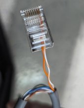
ethernet-pins.jpg


* Each ethernet connector is about 7" or 8" apart from the previous one, to match the space between RS485 connections in the batteries mounted in the rack.

rack.jpg

* Then all those wires go into 2 wagos: one for the solid colored wires and one for the others. They are 23 or 24 AWG and you can insert more than one wire per slot.
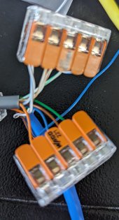
wagos.jpg


* And finally connected 2 more wires, solid and striped, from the wagos to my RS485 dongle, with the solid color wire going to B- and the other to A+ (pardon my crimping, wire was smaller than the ferrule :). All solid wires come from the ethernet pin 8 and are connected to B-, the others come from pin 7 and are connected to A+:
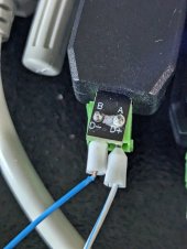
rs485.jpg

When I'm done with experiments, the wagos will be inside of the rack, on top of the first battery, and 2 tiny wires will come out from the hole on the left.

Please, share your RS485 bus setup, specially if you have something "minimalistic" like this.
Thanks.
 
The description from the Amazon link says "Features: -Antistatic, anit-jamming, stable performance. -Baud Rate Range: 75 ~ 115200 bsp; maximum speed up to 500 kbps".

It seems to be the exact same thing that I received with the batteries from signature solar, only that the SS one has some different internal number when I checked using udevadm test on Linux (same rs485 chip though).

At the moment I have 4 plugged to a mini PC and all seems to be good.
 
Sure, no isolation doesn’t affect signal integrity, but note that ethernet is required to be isolated and I believe RS485 is supposed to be isolated in best practice.

You sure you are OK with the potential of ground loop current going into your motherboard via USB? By default USB is not isolated though isolation transformers are available for USB2 data rates
 
Also the PCI ID isn’t going to tell you anything about what analog components are present in the dongle…

With the PC sitting on four separate RS485 buses the chances of an electrical altercation are probably elevated.
 
Also the PCI ID isn’t going to tell you anything about what analog components are present in the dongle…

With the PC sitting on four separate RS485 buses the chances of an electrical altercation are probably elevated.
I have one of these:
Screenshot_20230809-212638~2.png
To which my 2 inverters are connected: 2x RS232 for monitoring, 1 dongle from the inverter to battery Ethernet cable. Then 2 more dongles, one to battery ID#1 and one to the other 5 using Wagos. The inverter to battery cable and the PC to battery cable provided by signature solar do only use 2 wires each for A+ and B-.

Just to be clear, you are suggesting that I should use something like this isolator for each dongle? Or just for the one on which I'm currently using Wagos? Or maybe throw these dongles away and get isolated dongles like this?

What "electrical altercation" are we talking about? Some spike coming thru those wires from the inverters or the batteries? Would grounding the metal case of the minipc help? All these things are sitting on top of the EG4 battery rack, which is grounded and I could piggyback on that ground wire.

Thanks a lot.
 
Last edited:
I think you can use either transformer or optoelectronic isolation.

I don’t think the Wagos affect the risk that much.

I wasn’t talking about spikes but rather differences in ground potential, which is a function of how the power source for each device is configured, as well as the power up sequence. Personally if I don’t understand that/system is complicated it seems like cheap insurance.

This isn’t like say HDMI or USB2/3 where galvanic isolation is insanely expensive or untenable, thus the majority of systems forgo it.
 
Sure, no isolation doesn’t affect signal integrity, but note that ethernet is required to be isolated and I believe RS485 is supposed to be isolated in best practice.

You sure you are OK with the potential of ground loop current going into your motherboard via USB? By default USB is not isolated though isolation transformers are available for USB2 data rates
I had some time to read about galvanic isolation and, on top of upgrading the rs485 dongles, I ended up buying 2 RS232 isolators to be on the safe side there too.

I already had a Pi4 dying (memory error) when it was connected to both inverters OTG ports and I suspected it was related to the power on sequence because it happened right after I switched on the inverters. The fact that the Pi4 through the OTG port was able to keep the inverter LCD screen on when the inverters had no other source of power probably didn't help. RIP pi4.

Thank you so much.
 
Last edited:
No problem. I had forgotten to mention the fact that you can isolate the RS232 as well. I think none of these cables are shielded; if they were then you would want to be careful about creating ground loops through shield (usually the answer is to float one end)

I'm actually somewhat afraid of frying HDMI ports after learning about the possibility of messing up the powerup sequence. In practice, there's only a few niches where it probably bites people in the butt (like setting up videography equipment, which is another of my hobbies, where you can have batteries connected to multiple voltage converters for different equipment connected to each other, not all of which can be galvanically isolated at reasonable cost). Normal setups like AV are probably pretty idiot proof.

For solar & battery stuff, there's so many independent power sources flying around at different potential, some of them always powered (like the solar panels and the batteries), that it feels like an accident waiting to happen.

Another source of fried equipment is isolated vs non-isolated DC power supplies. Isolated is probably safer in general. Non-isolated = cheaper/more power for the same price, so you can probably assume anything unlabeled from Amazon or wherever is non-isolated.

Most common DIY electronics murder I can think of is powering cable modem from the wrong kind of PoE adapter. A lot of those are non-isolated, and will reference on an arbitrary choice of power pole from the ethernet (so you could have, say, 36V to 48V from earth potential come out of a 12V power extractor. The exact voltage is also a function of how the power injector is designed). But the single ended coax signal is referenced against earth potential, so a cool 48V will go through the driver chip.
 
Back
Top