The battery has a comms cable to the battery and inverter. Its a seperate cableDo you split your 'connection' so that the inverter is connected to battery #1 as well? I still want my inverter to be aware of SOC.
I currently have my master battery connected on the CAN port to the inverter. Then the batteries below it are connected via the ethernet comm cables that shipped with the batteries. I assume this is what you mean with your "chain the rest"?


You are using an out of date browser. It may not display this or other websites correctly.
You should upgrade or use an alternative browser.
You should upgrade or use an alternative browser.
Solar assistant questions
- Thread starter bajarick
- Start date
Kenny_
Solar Addict
No, see above.... Inverter is connected to battery #1 RS485A port, SA/raspberry pi is connected to battery #1 Rs232/console port.Do you split your 'connection' so that the inverter is connected to battery #1 as well? I still want my inverter to be aware of SOC.
I currently have my master battery connected on the CAN port to the inverter. Then the batteries below it are connected via the ethernet comm cables that shipped with the batteries. I assume this is what you mean with your "chain the rest"?
The inverter (at least mine) doesn't seem to know/see multiple batteries...it does get alarms etc..
Kenny_
Solar Addict
You're probably best asking Solar Assistant about that. I've found there tech support quite responsive!So my Raspberry Pi lunched my SD card with Solar Assistant and I had to download my image again and build a new Pi. The problem is, it wants me to activate a new device and it won't let me use the old activation. Is there an easy way to replace the Solar Assistant on a Pi?
Brett V
Mad Scientist
Activation is paired with the Pi device, not the download image. If you’ve installed a different device, you will have to use your one time transfer.So my Raspberry Pi lunched my SD card with Solar Assistant and I had to download my image again and build a new Pi. The problem is, it wants me to activate a new device and it won't let me use the old activation. Is there an easy way to replace the Solar Assistant on a Pi?
dmkjr
Solar Enthusiast
I have the LifePower4 batteries. Has two ports. First port of battery one goes to inverter. Port two goes to battery two and so forth.No, see above.... Inverter is connected to battery #1 RS485A port, SA/raspberry pi is connected to battery #1 Rs232/console port.
The inverter (at least mine) doesn't seem to know/see multiple batteries...it does get alarms etc..
Is there a method to run communication to SA and my Inverter?
marionw
Solar Enthusiast
The EG4 LifePower4 batteries have both the RJ45 jacks in parallel, that is to say pin1 to pin1, pin2 to pin2 etc.
Is your first batteries address set to 0 (all switches down). Is so this battery is in master mode and polls the other batteries on pins 7 & 8 (either RJ45 jack). The master battery collects the data from all the others and sends the data to the inverter (when asked by the inverter) as if it were one big battery.
The inverter would then be connected to the battery stack on pins 1&2 as the inverter is also a "master" and you can't have two "masters" (SA is also a master) on the same RS485 bus.
A master sends a command, waits for the response and knows how to handle the response because it know what data was requested. Imagine however the response it received was the result of a request from the other master on the same bus. In other words is you have two masters on the same bus sendiing commands/requests, the other master would get confused. In addition the BMS can't handle being flooded with commands, the BMS must be given time to respond to the request.
Not sure how SA or the inverter will handle being on the same bus as they are both "masters"
I have 6 EG4 LifePower4 batteries connected to a SunGoldPower 10kw inverter. I use an EG4 Communications hub between the batteries and the inverter. The hub acts just like one of the EG4 batteries in "master" mode so I don't have any of the batteries address set to 0. Since the Inverter is connected to the output/inverter connection on the hub, pins 1&2 RS485 bus on the batteries is not being used so my SA connected to these tow pins has no issues with communication conflicts. There are a number of protocol options you can assign to the hub's inverter port output to match whatever is set on the inverter for it's bms protocol. My SA is also connected to the Wifi port on the inverter so SA is happy and it has not dropped offline or lost communications with either the inverter or batteries. Unfortunately the battery input port on the EG4 hub does not have a selectable bms protocol (it is set to EG4 only) otherwise it would solve the SA issues with my SunGoldPower batteries.
There are a number of folks on this forum who are experiencing issues with SA and I expect most are the result two masters on the same bus.
I know this is lengthy but stick with it, there is a solution out there somewhere, the only question is; is it affordable.
dmkjr
Solar Enthusiast
I have an EG4 Communications Hub but I have custom built batteries, so guess that will not work.
marionw
Solar Enthusiast
I appologize, I throught from above "I have the LifePower4 batteries. Has two ports. First port of battery one goes to inverter. Port two goes to battery two and so forth." that you had EG4 batteries, I might have misread.
Do you know the Make/Model of the batteries and what BMS is in the batteries?
Do you know the Make/Model of the batteries and what BMS is in the batteries?
Kenny_
Solar Addict
I see. I'm not familiar with that communication setup so disregard my comments which are all Sungold related!I have the LifePower4 batteries. Has two ports. First port of battery one goes to inverter. Port two goes to battery two and so forth.
Is there a method to run communication to SA and my Inverter?
dmkjr
Solar Enthusiast
Ahh, I guess I should have elaborated better. I have more than one solar setup. I have a house that has EG4 batteries and my primary residence, I have custom built batteries, Seplos. Believe it is JK BMs.I appologize, I throught from above "I have the LifePower4 batteries. Has two ports. First port of battery one goes to inverter. Port two goes to battery two and so forth." that you had EG4 batteries, I might have misread.
Do you know the Make/Model of the batteries and what BMS is in the batteries?
Finally got all 4 to show up! Turns out it was the battery addresses that was not correct!No, see above.... Inverter is connected to battery #1 RS485A port, SA/raspberry pi is connected to battery #1 Rs232/console port.
The inverter (at least mine) doesn't seem to know/see multiple batteries...it does get alarms etc..
Attachments
Kenny_
Solar Addict
Excellent!Finally got all 4 to show up! Turns out it was the battery addresses that was not correct!
marionw
Solar Enthusiast
Could you please share which system, batteries and what you did to fix the problem?
jsmithtx
New Member
What is the RS232 port? My first two batteries are the LL-S and they have 4 total ethernet ports (see page 6 of manual), in the following order (connections are for the first battery):No, see above.... Inverter is connected to battery #1 RS485A port, SA/raspberry pi is connected to battery #1 Rs232/console port.
The inverter (at least mine) doesn't seem to know/see multiple batteries...it does get alarms etc..
- CAN --> To Inverter
- RS485
- Battery-Comm
- Battery-Comm --> To next battery
Kenny_
Solar Addict
You may not have a RS232/Console port like the Sungold batteries and the Pace BMS controller...
Sungold SP6548 Inverter and 2 Sungold wallmount batteries and two rackmount batteries. The issue was the battery addresses.Could you please share which system, batteries and what you did to fix the problem?
marionw
Solar Enthusiast
Let me see if I understand (only cause a lot of folks have SGP batteries and inverters)
One SGP battery address is set to 0 and the others are 1,2,3.
The inverter is connected to the CAN port on battery 0.
Battery 0 polls the other batteries on the Battery-Comm ports (both because you have them daisy chained)
Is Solar Assistant connected to the RS485 port which is next to the CAN Port? And if so is SA showing all four batteries?
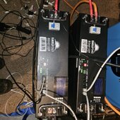
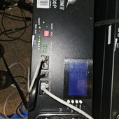
Battery 1 is connected to inverter via RS485A. RS485B connects from battery 1 to battery 2 RS485C Battery 2 RS485B connects Battery 3 RS485C etc. Solar Assistant connects to PI from RS232 port on battery and inverter
Battery 1 would have battery 0000 address. The others as the manual shows. Also the cable going from the battery to the inverter is a special cable that can only work one way. Each end is marked, one inverter and the other battery.
Battery 1 would have battery 0000 address. The others as the manual shows. Also the cable going from the battery to the inverter is a special cable that can only work one way. Each end is marked, one inverter and the other battery.
Attachments
Kenny_
Solar Addict
Pretty sure battery 1 must be set to address 1 for this to work (which btw is identical to my setup with Sungold equipment, but maybe your Sungold inverter works with address 0...mine requires address 1 for first battery)Battery 1 is connected to inverter via RS485A. RS485B connects from battery 1 to battery 2 RS485C Battery 2 RS485B connects Battery 3 RS485C etc. Solar Assistant connects to PI from RS232 port on battery and inverter
Battery 1 would have battery 0000 address. The others as the manual shows. Also the cable going from the battery to the inverter is a special cable that can only work one way. Each end is marked, one inverter and the other battery.
I assume your PI is also connected to the inverter via USB (not sure if you have a Sungold inverter or not).
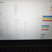
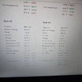
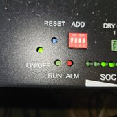
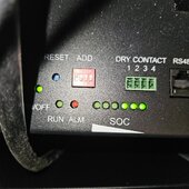
Actually when battery 1 was set to 1000 it wouldn't work right. Set it to 0000 and boom it started showing in SA and no comms error on SP6540 inverter. First Pic is battery 0000 which is battery 1, second is battery 2 1000 and third pic shows no comms error on inverter.Pretty sure battery 1 must be set to address 1 for this to work (which btw is identical to my setup with Sungold equipment, but maybe your Sungold inverter works with address 0...mine requires address 1 for first battery)
I assume your PI is also connected to the inverter via USB (not sure if you have a Sungold inverter or not).
Attachments

Similar threads
- Replies
- 21
- Views
- 435
- Replies
- 1
- Views
- 179
- Replies
- 15
- Views
- 868