diy solar

diy solar

Solar/Electrical Noob needs help reviewing a electrical system diagram

QuantumRaptor

New Member
Joined
Jul 18, 2023
Messages
5
Location
Atlanta Georgia
Hey all!

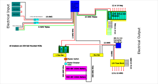
As the title explains I need help reviewing the electrical diagram I drew up of my system (above). I am converting an old ambulance into a camper. If you see anything wrong with this setup please tell me so I don't burn down my future home. :?

I'm also wondering if DIN Rail mounted miniature circuit breakers are the right choice for both my AC and DC inputs/outputs. I do plan on using blade fuses for the 12v circuits themselves but for the rest I would like to use breakers (DIN mounted MCBs specifically).

Also I do already have the following componants: Inverter/charge/solar charge converter combo (EG4 3000EHV-48, batteries(2x EG4 48V 100Ah), fuse block (with fuses), 48v to 12v converter, and some of the smaller wires.

Thanks so much for any help!Electrical System DrawingV1.png
 
Nice job. You got all the little things I usually find missing.

You may (or may not) want to consider a switch between the bus bar and the inverter- that way if any maintenance needs done the 12v stuff can stay active.

I am assuming that all wire runs between the battery and inverter/fuse boxes are short and in the same compartment. If not addition fuses may be needed.
Thanks!
A switch on the inverter might be a good idea, would it make a difference if it were placed in on the bus bar side of the fuse or the inverter side?

Also would DIN Mounted MCBs work for this application? I've seen lots of people saying they work great and recommend them or whatever, but there are also a few people who have said they should not be used in this situation. Do you have any experience with them?

And it's probably complex to answer but do the wire guages and fuse sizings seem okay to you?

Thanks again!!!
 
Wire size ok.
Fuses:
12ga wires to converter - fuse size of 35a is too high - I think should be 20a

Breaker of 100a might be too low - then have a fuse of 125a - which is ok for 2awg wire.
 
Wire size ok.
Fuses:
12ga wires to converter - fuse size of 35a is too high - I think should be 20a

Breaker of 100a might be too low - then have a fuse of 125a - which is ok for 2awg wire.
Noted.
For the breaker on the battery if I put two batteries in parallel would their max output current increase accordingly? So each battery is rated for a 100a output so since theyre in parallel would the max output be 200a or stay at 100a?
 
Noted.
For the breaker on the battery if I put two batteries in parallel would their max output current increase accordingly? So each battery is rated for a 100a output so since theyre in parallel would the max output be 200a or stay at 100a?
It would be a 200Ah battery.
However, you only have to ensure that you fuse (or breaker) for the wire size you are using.
For example if your max load is going to be 100A and you have a 600A battery rack. you don't have to use a 600A fuse (or breaker).
In that case, I would use a 125A, or 150A and make sure the wire will handle that current.
Breakers and fuses are to protect the wire.
Your 000 battery wiring is definitely capable of handling the amperage.
 
Last edited:
Back
Top